
Device for estimating machining dimension of machine tool

a machine tool and dimension technology, applied in the direction of manufacturing tools, program control, instruments, etc., can solve the problems of wasting workpieces, machining dimension errors, and deemed defective machines, and achieve the effect of reducing workpiece was

Inactive Publication Date: 2008-04-03
MATSUSHITA ELECTRIC WORKS LTD
View PDF6 Cites 10 Cited by
  • Summary
  • Abstract
  • Description
  • Claims
  • Application Information

AI Technical Summary

Benefits of technology

[0005]In view of the above, the present invention provides a device for estimating a machining dimension of a machine tool prior to machining a workpiece to thereby reduce the waste of the workpiece caused by the machining dimension falling outside of the tolerance.
[0008]In this configuration, the machining dimension is estimated by using amounts of characteristics from output of the vibration sensor based on a point that a distribution of amounts of characteristics from the output of the vibration sensor while a tool member attached to a machine tool are racing and a distribution of machining dimensions when workpieces are machined by the corresponding tool member are related. Since machining dimension is estimated prior to machining the workpiece, it is prevented that a workpiece is not machined precisely due to an unproperly attached tool member. As a result, fabricating a defective workpiece is prevented.
[0010]In this configuration, even if there are various kinds of tool members, the machining dimensions of respective kinds of tools can be estimated. Therefore, even in case of a machining center or the like which performs machining by automatically replacing a tool member with another, a workpiece is prevented from being machined wastefully by estimating machining dimensions of respective tools.

Problems solved by technology

However, even if the tool is adequately attached to the driving unit not to incur difficulties in machining a workpiece, some errors in a machining dimension can occur due to, e.g., misalignment of shaft axis, and improper attachment wear, and broken edges of the tool.
Therefore, there is no problem if the machining dimension is within the tolerance range, but if the machining dimension is out of the tolerance range, the machined workpiece is deemed to be defective.
The machining dimension can be known only after completing the machining, resulting in a waste of workpiece.

Method used


Image

  • Device for estimating machining dimension of machine tool
  • Device for estimating machining dimension of machine tool
  • Device for estimating machining dimension of machine tool

Examples


Embodiment Construction

[0022]Embodiments of the present invention will now be described with reference to the accompanying drawings which form a part hereof.

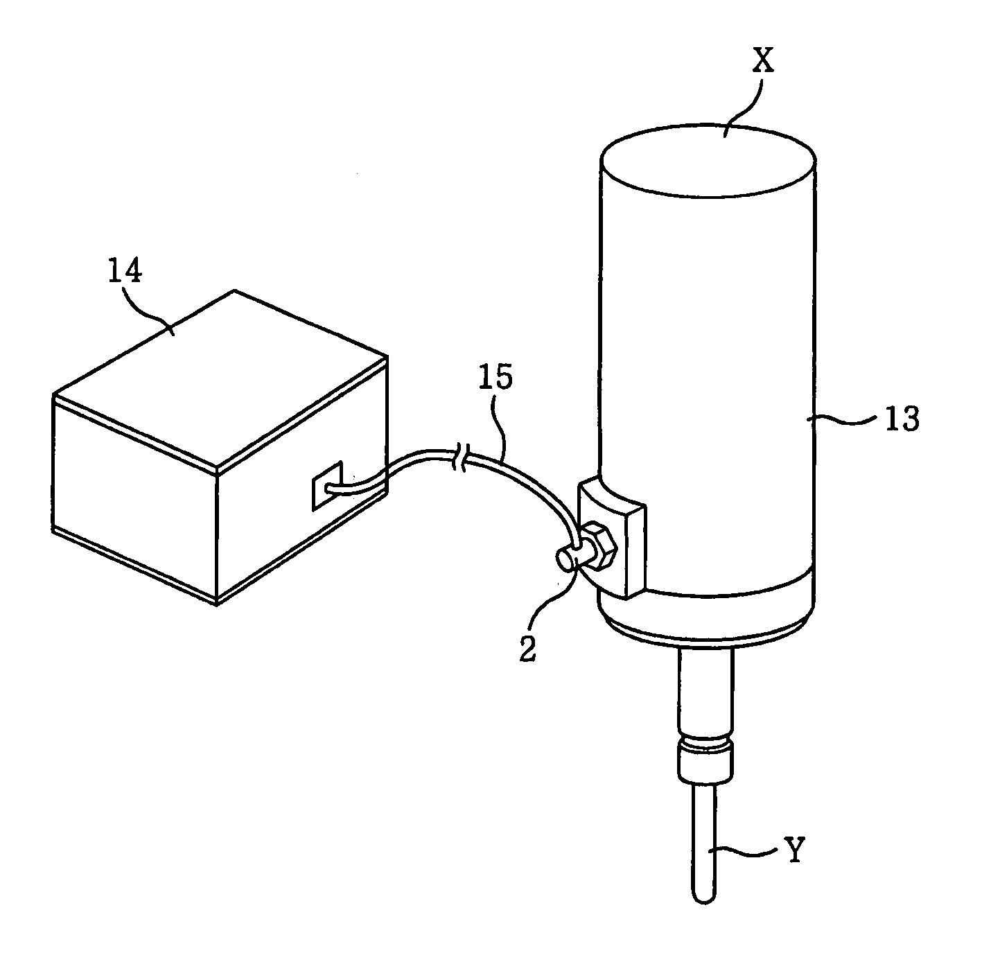
[0023]A machine tool exemplified in an embodiment described below is a machining center or a turning center in which a tool to be used is automatically selected according to a program from a plurality of tools held in a tool magazine and is automatically mounted to a driving unit. However, the present invention can be also applicable to a machine tool with a single function if a tool is rotatably driven by a driving unit having a driving source such as a motor. Any driving source using a motor can serve as a driving unit, and a proper power transmission unit such as a gearbox or a belt can be provided between the driving source and the tool. Hereinafter, a spindle with a housing is exemplified as a driving unit.

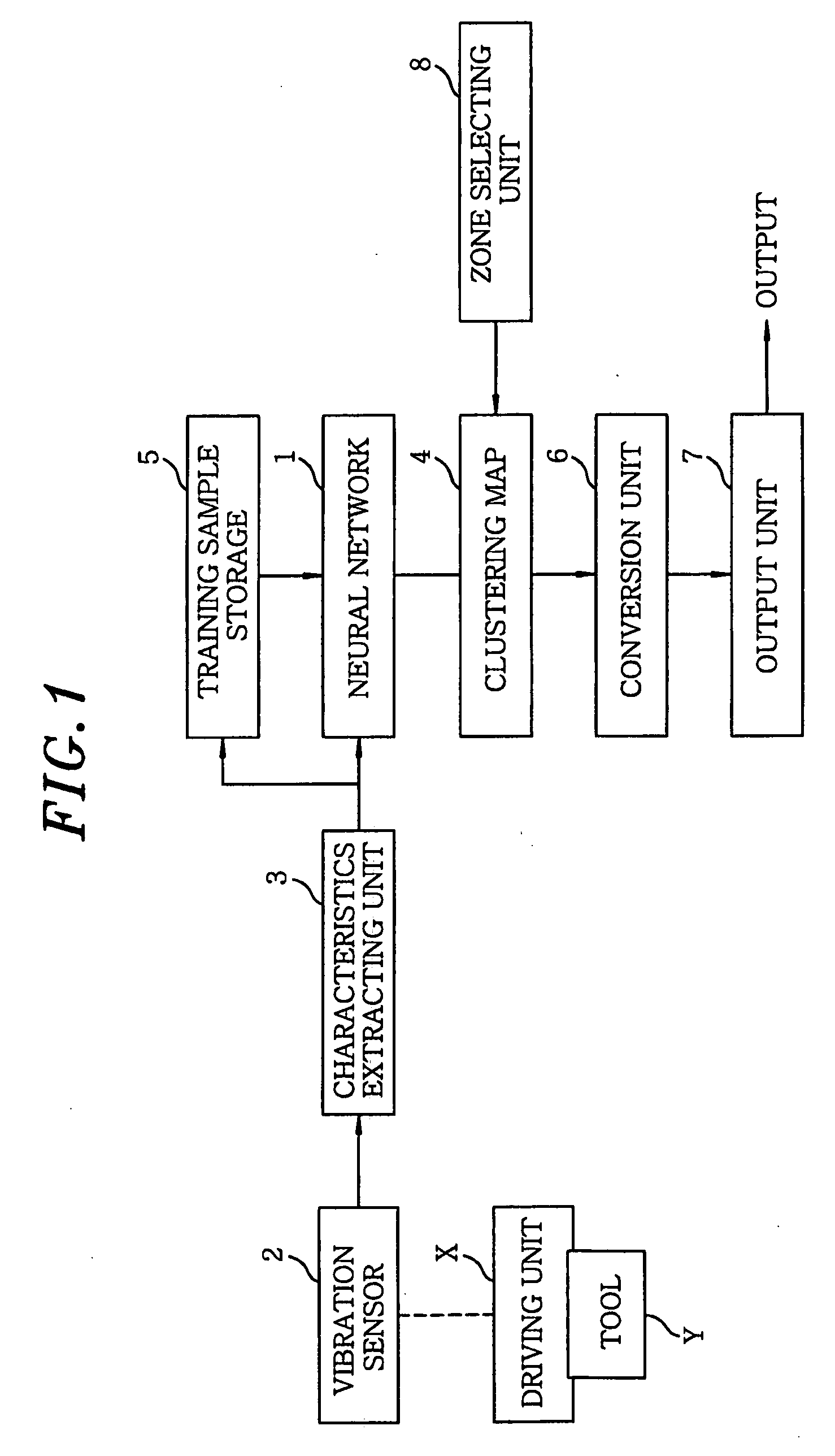
[0024]As shown in FIG. 1, a device for estimating machining dimensions of a machine tool described in the present embodiment uses, e.g., an un...


PUM

PropertyMeasurementUnit
Dimensionaaaaaaaaaa
Distanceaaaaaaaaaa

Abstract

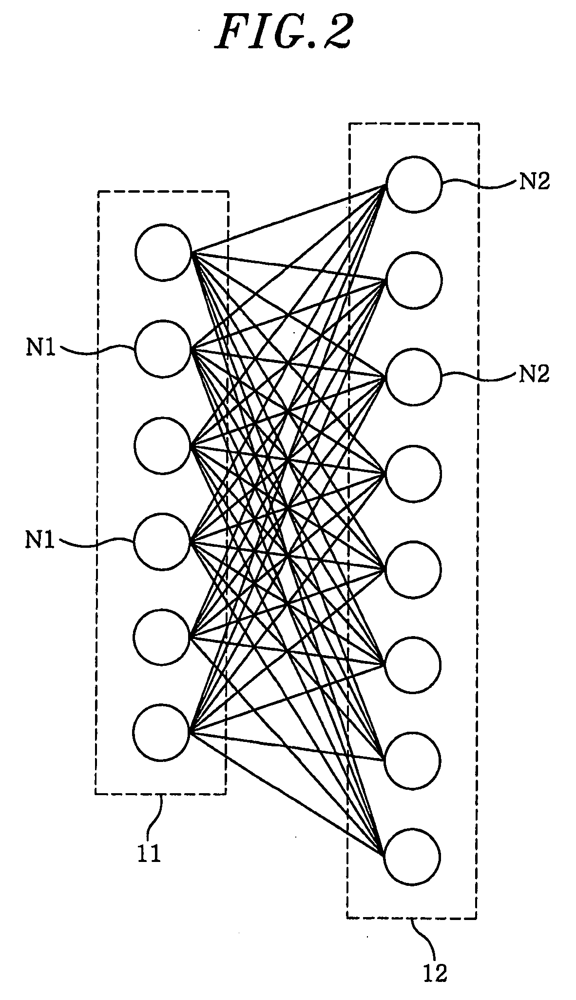
A device for estimating machining dimensions of a machine tool which employs tool members each being rotatably driven by a driving unit includes: a vibration sensor; a characteristics extracting unit for extracting amounts of characteristics from an output of the vibration sensor; a neural network for classifying the amounts of characteristics into categories; and a conversion unit. Amounts of characteristics of generated output by racing the tool member are used for training the neural network, and inputted again to the trained competitive learning neural network to excite neurons so that the relationships between Euclidean distances and machining dimensions of workpieces are registered in the conversion unit. The Euclidean distances are obtained between weight vectors of the excited neurons and respective corresponding training samples, and the machining dimensions are obtained when the workpieces are machined by the tool members at the same condition as the respective corresponding training samples are obtained.

Description

FIELD OF THE INVENTION [0001]The present invention relates to a device for estimating machining a dimension of a machine tool; and, more particularly, to a device for estimating, prior to machining a workpiece, a machining dimension of a machine tool which has tools rotatably driven by a driving unit including a driving source such as a motor, depending on attachment states of the tools.BACKGROUND OF THE INVENTION [0002]Conventionally, in an automatic tool changer of a numerical control machine tool, there has been proposed a device to monitor an anomaly in tool change operation of a tool change arm (see, e.g., Japanese Patent Laid-open Application No. H11-333657). The device detects torque waveform pattern of a driving motor generated when the tool change arm is at various positions on a track thereof being made while performing the change operation. The detected torque waveform pattern is compared with that of the driving motor generated while the tool change arm operated normally...

Claims


Application Information

Patent Timeline
IPC IPC(8): G06F19/00B23Q3/155B23Q17/12
CPCG05B19/406G05B2219/33296Y10T409/309576Y10T82/2595G05B2219/37435
Inventor IKEDA, KAZUTAKA
Owner MATSUSHITA ELECTRIC WORKS LTD
Learn More