
Resist composition and pattern forming method using the same

a composition and resist technology, applied in the field of resist compositions, can solve the problems of reducing yield, reducing the resolution, and not yet meeting the requirements of high resolution, high sensitivity and low development defect, and achieve the effects of reducing the development defect, high resolution, and high sensitivity

Inactive Publication Date: 2008-04-03
FUJIFILM CORP
View PDF6 Cites 5 Cited by
  • Summary
  • Abstract
  • Description
  • Claims
  • Application Information

AI Technical Summary

Benefits of technology

[0010] An object of the present invention is to provide a resist composition capable of realizing high resolution, high sensitivity and reduction in the development defect after pattern formation and thereby increasing the yield in a fine processing of a semiconductor device, where actinic ray or radiation, particularly, KrF excimer laser light, electron beam or EUV light, is used, and a pattern forming method using the resist composition.

Problems solved by technology

At the formation of an ultrafine pattern in the sub-micron or quarter-micron region by a lithography process using KrF excimer laser light, electron beam or EUV light, the first condition is sufficiently high resolving power, but the resist film is also thinned to a sub-micron order and in the case of an ultrafine pattern in the sub-micron or quarter-micron region, even a fine defect of sub-micron order is transferred at the etching using the resist pattern as the mask and causes serious reduction in the electric characteristics, as a result, the yield decreases.
However, it is not yet achieved at present to satisfy high resolution, high sensitivity and low development defect all at the same time in the ultrafine region.

Method used


Image

  • Resist composition and pattern forming method using the same
  • Resist composition and pattern forming method using the same
  • Resist composition and pattern forming method using the same

Examples


synthesis example 1

Synthesis of Resin A-40 as the Resin (A)

[0186] Acetoxystyrene and 1-phenylethyl methacrylate were charged at a ratio of 90 / 10 (by mol) and dissolved in cyclohexanone to prepare 100 ml of a solution having a solid content concentration of 20 mass %. Subsequently, 2 mol % of a polymerization initiator, V-601, produced by Wako Pure Chemical Industries, Ltd. was added thereto, and the resulting solution was added dropwise to 10 ml of cyclohexanone heated at 80° C., over 4 hours in a nitrogen atmosphere. After the completion of dropwise addition, the reaction solution was heated for 4 hours, and 1 mol % of V-601 was again added, followed by stirring for 4 hours. After the completion of reaction, the reaction solution was cooled to room temperature and then crystallized in 3 L of hexane, and the precipitated white powder was collected by filtration.

[0187] The compositional ratio of the polymer determined from C13NMR was 89 / 11 (by mol). Also, the weight average molecular weight determine...


PUM

PropertyMeasurementUnit
carbon numberaaaaaaaaaa

Abstract

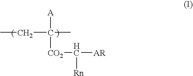
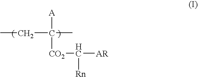
A resist composition, comprises: (A) a resin containing a repeating unit represented by formula (I); (B) a compound capable of generating an acid upon irradiation with actinic rays or radiation; and (C) a solvent containing: (C1) a propylene glycol monoalkyl ether carboxylate; and (C2) at least one member selected from the group consisting of a propylene glycol monoalkyl ether, an alkyl lactate, an acetic acid ester, an alkyl alkoxypropionate, a chain ketone and a cyclic ketone: wherein AR represents a substituted or unsubstituted benzene ring or a substituted or unsubstituted naphthalene ring; Rn represents a substituted or unsubstituted alkyl group, a substituted or unsubstituted cycloalkyl group or a substituted or unsubstituted aryl group; and A represents a hydrogen atom, a substituted or unsubstituted alkyl group, a substituted or unsubstituted cycloalkyl group, a halogen atom, a cyano group or a substituted or unsubstituted alkyloxycarbonyl group, and the pattern forming method uses the same.

Description

BACKGROUND OF THE INVENTION [0001] 1. Field of the Invention [0002] The present invention relates to a positive resist composition suitable for use in the ultramicrolithography process such as production of VLSI or a high-capacity microchip or in other photofabrication processes. More specifically, the present invention relates to a positive resist composition capable of forming a high-resolution pattern by using KrF excimer laser light, electron beam, EUV light or the like, that is, a positive resist composition suitably usable for fine processing of a semiconductor device, where KrF excimer laser light, electron beam or EUV light is used, and a pattern forming method using the composition. [0003] 2. Description of the Related Art [0004] In the process of producing a semiconductor device such as IC and LSI, fine processing by lithography using a photoresist composition has been conventionally performed. Recently, the integration degree of an integrated circuit is becoming higher an...

Claims


Application Information

Patent Timeline
Patent Type & Authority Applications(United States)
IPC IPC(8): G03C1/73G03C5/00
CPCG03F7/0048G03F7/0397G03F7/0392
Inventor NISHIYAMA, FUMIYUKIMIZUTANI, KAZUYOSHIMAKINO, MASAOMISUGIYAMA, SHINICHI
Owner FUJIFILM CORP
Learn More