Electron Lens and Charged Particle Beam Apparatus

a technology of charged particle beam and electron lens, which is applied in the direction of discharge tube/lamp details, magnetic discharge control, instruments, etc., can solve the problems of affecting the operation adversely affecting the magnetic leakage of electron optical system or any other apparatus located outside the lens, and hazarding the use of the sem or performing maintenance work. , to achieve the effect of high resolution

Inactive Publication Date: 2008-03-20
HITACHI HIGH-TECH CORP
View PDF13 Cites 39 Cited by
  • Summary
  • Abstract
  • Description
  • Claims
  • Application Information

AI Technical Summary

Benefits of technology

[0028]According to the present invention, there is provided a compact electron lens causing little aberration, and a charged particle beam apparatus such as an SEM that is super compact and offers a high resolution.

Problems solved by technology

However, the permanent magnet externally induces leakage flux.
The magnetic leakage adversely affects an electron optical system or any other apparatus located outside the lens.
This hazards a person who uses the SEM or performs maintenance work.
This leads to an increase in the magnitude of magnetic flux moving outside.
Therefore, a magnetic field realizing the lens gets weakened, and the lens structure does not function as a lens any longer.
However, the adoption of the lens structure as an objective lens to be included in a compact SEM poses a problem in that that the size of the objective lens gets large.
Therefore, aberration cannot be reduced.
This poses a problem in that a high resolution can hardly be attained.

Method used


Image

  • Electron Lens and Charged Particle Beam Apparatus
  • Electron Lens and Charged Particle Beam Apparatus
  • Electron Lens and Charged Particle Beam Apparatus

Examples


first embodiment

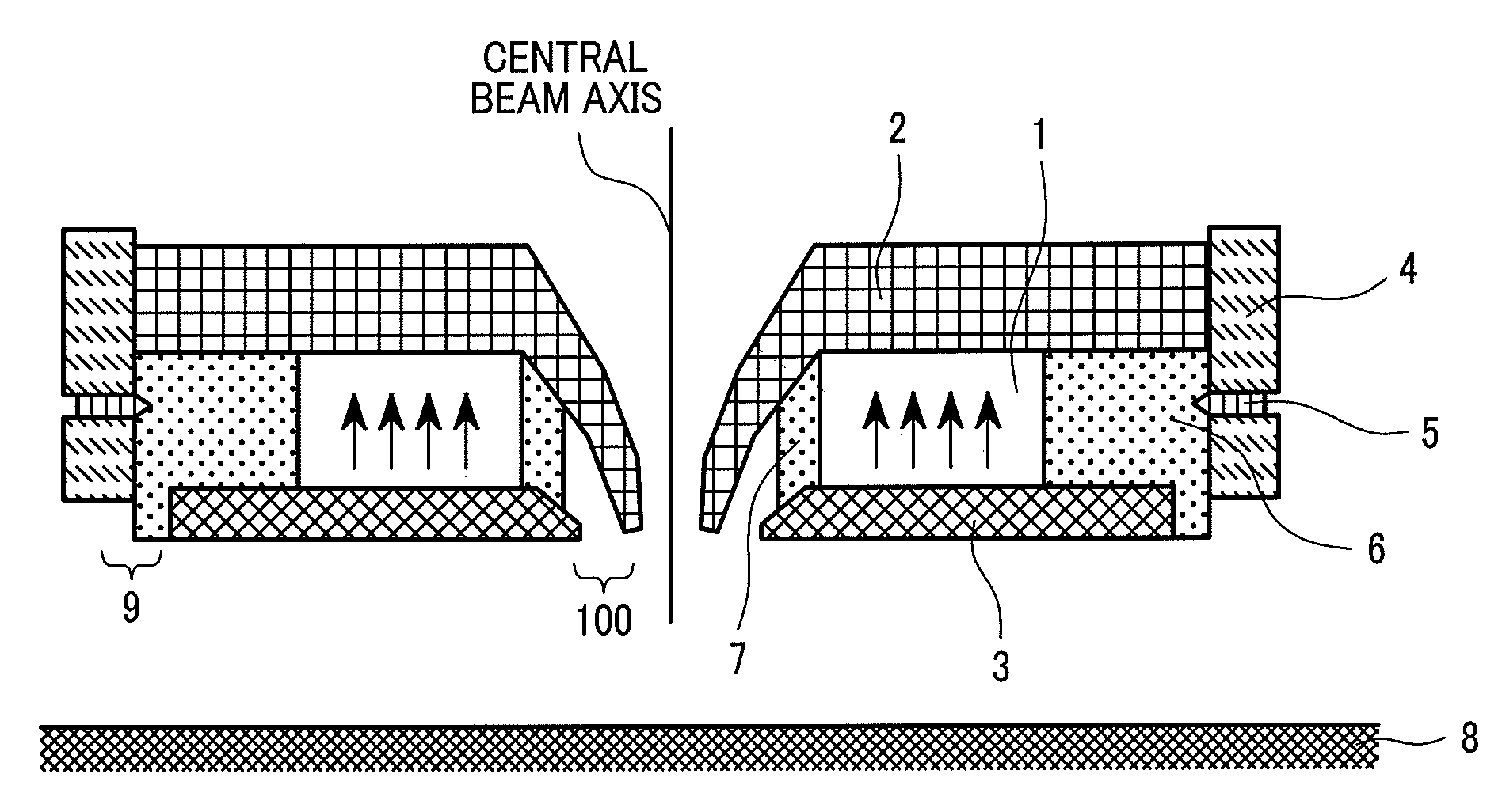
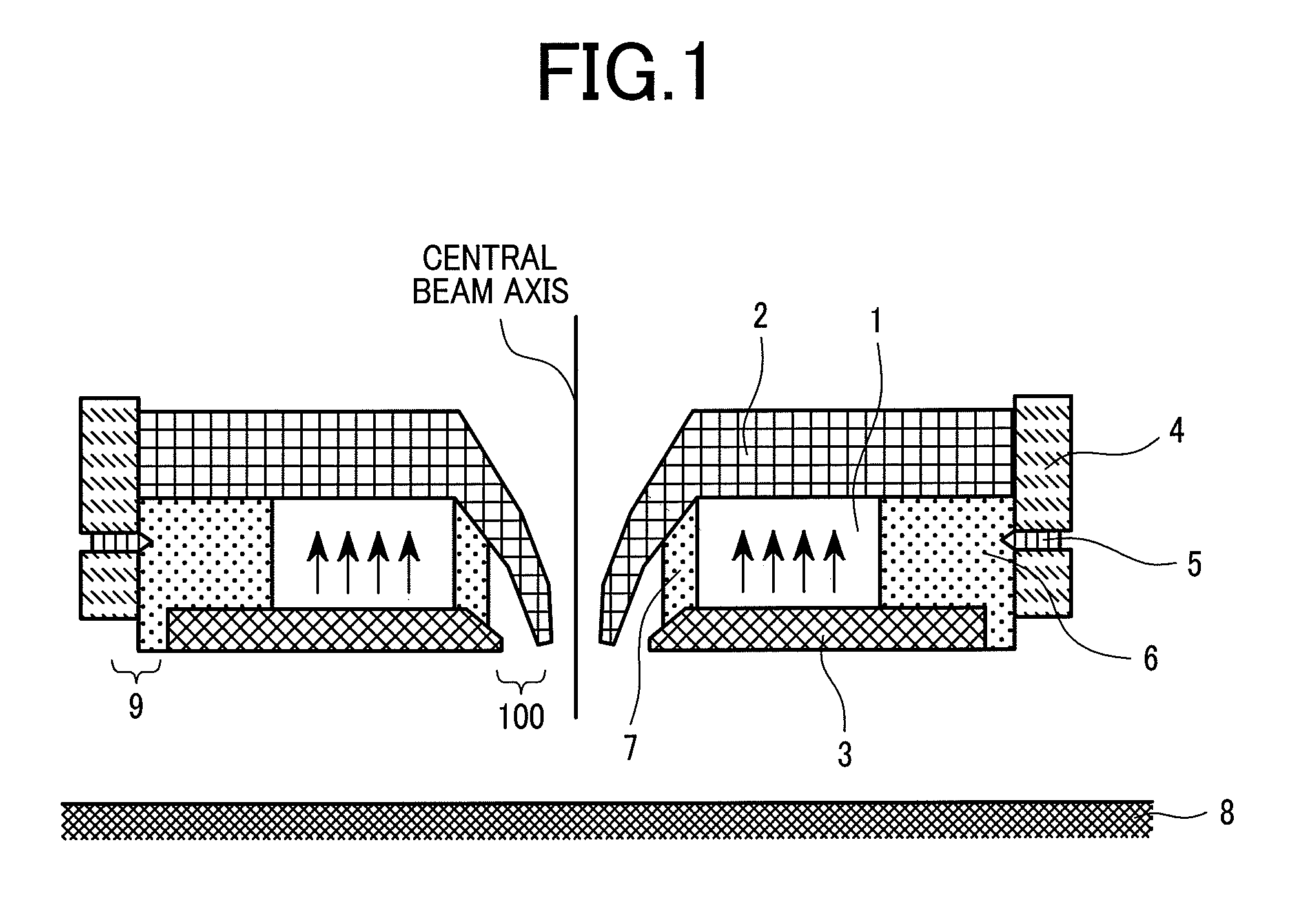
[0041]FIG. 1 shows a cross section of a structure serving as an electron lens (compact objective lens) according to the first embodiment of the present invention. A permanent magnet 1 having a hole in the center thereof, having an axially symmetrical shape (doughnut shape), and exhibiting axially symmetrical magnetism is magnetized vertically in the drawing and has an upper magnetic pole 2 and a sample-side magnetic pole 3, which are made of a permalloy, attached to the respective poles thereof. An inner gap 100 created between the magnetic poles is oriented to a sample near the axis. Flux is generated in a vacuum from the gap, and an axial magnetic field is induced on the center axis of the lens structure on the side of a sample, that is, below the lens structure. The magnetic field functions as a magnetic lens. The peak of a magnetic flux density is on the order of 0.2 Tesla. A working distance (WD) ranges from about 2 mm to about 4 mm. The magnetic lens is optimal for an electron...

second embodiment

[0065]FIG. 7 shows the second embodiment of the present invention implemented in a compact electrostatic column in order to attain a high resolution.

[0066]Herein, an electron gun 70 is exhausted using a sheet-type non-evaporable getter pump 72, which is disposed inside, instead of an ion pump. This is intended to employ a high-performance Schottky electron beam source 71 and attain a compact design. The outer diameter of the electron gun 70 including the pump is as small as 70 mm or less. For startup, a vacuum pipe is extended from a rough exhaust port 69 and coupled to a turbo molecular pump 19. After the electron gun is exhausted to somewhat create a vacuum therein, a heater 73 disposed on the external wall thereof is used to heat or activate the non-evaporable getter pump 72. Thereafter, the rough exhaust port 69 is sealed with a valve. Consequently, the interior of the electron gun 70 is retained in a super vacuum atmosphere. Heating conditions for activation are such that the n...

third embodiment

[0075]FIG. 9 shows the configuration of the third embodiment of the present invention.

[0076]Illustrated is an apparatus suitable for observing as a sample 8 a wiring pattern in a semiconductor substrate or the shape of a hole therein. An electron beam 10 generated by an electron gun 70 employing a Schottky electron beam source is narrowly converged by a condenser lens 93 realized with a magnetic field and a magnetic objective lens 74 in accordance with the present invention, and irradiated to the sample 8. The electron beam 10 is swept by a beam deflector 16. An ExB filter 90 is disposed above the objective lens 74. The ExB filter 90 is designed to apply an electric field and a magnetic field orthogonally to each other and to the axis, and to regulate the electron beam 10 so that the electron beam 10 will advance rectilinearly. The ExB filter 90 bends the trajectory of passing electrons that is low in an energy level. Assuming that an amount of energy gained by the electron beam 10 ...


PUM


Abstract

The present invention provides a compact electron lens causing little aberration, and a charged particle beam apparatus such as a scanning electron microscope that is super compact and offers a high resolution. An upper magnetic pole and a sample-side magnetic pole are magnetically coupled to the respective poles of a permanent magnet that is made of a highly strong magnetic material such as a rare-earth cobalt system or a neodymium-iron-boron system, that is axially symmetrical, and that has a hole in the center thereof. An inner gap is created on the side of a center axis. Thus, a magnetic lens is formed axially. Moreover, a semi-stationary magnetic path that shields an outside magnetic field and has the magnetic reluctance thereof regulated is disposed outside. The sample-side magnetic pole and magnetic path defines a region where magnetic reluctance is the highest outside the permanent magnet. A space defined by the permanent magnet, upper magnetic pole, sample-die magnetic pole, and semi-stationary magnetic path is filled with a filling made of a non-magnetic material. Thus, an objective lens is constructed.

Description

CLAIM OF PRIORITY[0001]The present invention claims priority from Japanese Application JP2006-137815 filed on May 17, 2006, the content of which is hereby incorporated by reference on to this application.BACKGROUND OF THE INVENTION[0002](1) Field of the Invention[0003]The present invention relates mainly to an electron beam application technology adaptable to a scanning electron microscope (SEM) that uses an electron beam to permit observation of a microstructure.[0004](2) Description of the Related Art[0005]A magnetic lens composed of coils and a magnetic circuit is usually adopted as an objective lens to be included in conventional scanning electron microscopes (SEM). A strong magnetic field is needed in order to focus a beam of electrons on a microscopic point, and an amount of current flowing through the coils has to be increased accordingly. Therefore, measures have to be taken against a rise in temperature caused by heat dissipated from the coils. Namely, a thick wire is wound...

Claims


Application Information

Patent Timeline
Patent Type & Authority Applications(United States)
IPC IPC(8): H01J1/50
CPCH01J37/143H01J37/28H01J2237/31749H01J2237/2813H01J2237/1405
Inventor OHSHIMA, TAKASHISATO, MITSUGUKANEKO, YUTAKAKATAGIRI, SOUICHITAKEUCHI, KOICHIRO
Owner HITACHI HIGH-TECH CORP
Why Eureka
Try Eureka