
Valve timing control system

a timing control and valve technology, applied in the direction of non-mechanical valves, couplings, machines/engines, etc., can solve the problems of increasing the cost, deteriorating the flexibility of mounting, and deteriorating the response in advance operation, so as to reduce the number of components and improve the accuracy of synchronization

Active Publication Date: 2008-03-20
DENSO CORP +1
View PDF4 Cites 20 Cited by
  • Summary
  • Abstract
  • Description
  • Claims
  • Application Information

AI Technical Summary

Benefits of technology

[0022]The present invention addresses the above disadvantages. Thus, it is an objective of the present invention to provide a valve timing control system, which improves accuracy in synchronization between a phase control valve and a drain switch valve and mounting flexibility while enabling a reduction in a number of components.

Problems solved by technology

This may possibly deteriorate the response in the advance operation.
Furthermore, when the OSV 29 is installed separately from the OCV 22, the mounting flexibility may be deteriorated.
Also, when the OSV 29 is installed separately from the OCV 22, the number of components is increased to cause an increase in the cost.

Method used


Image

  • Valve timing control system
  • Valve timing control system
  • Valve timing control system

Examples


first embodiment

Advantages of First Embodiment

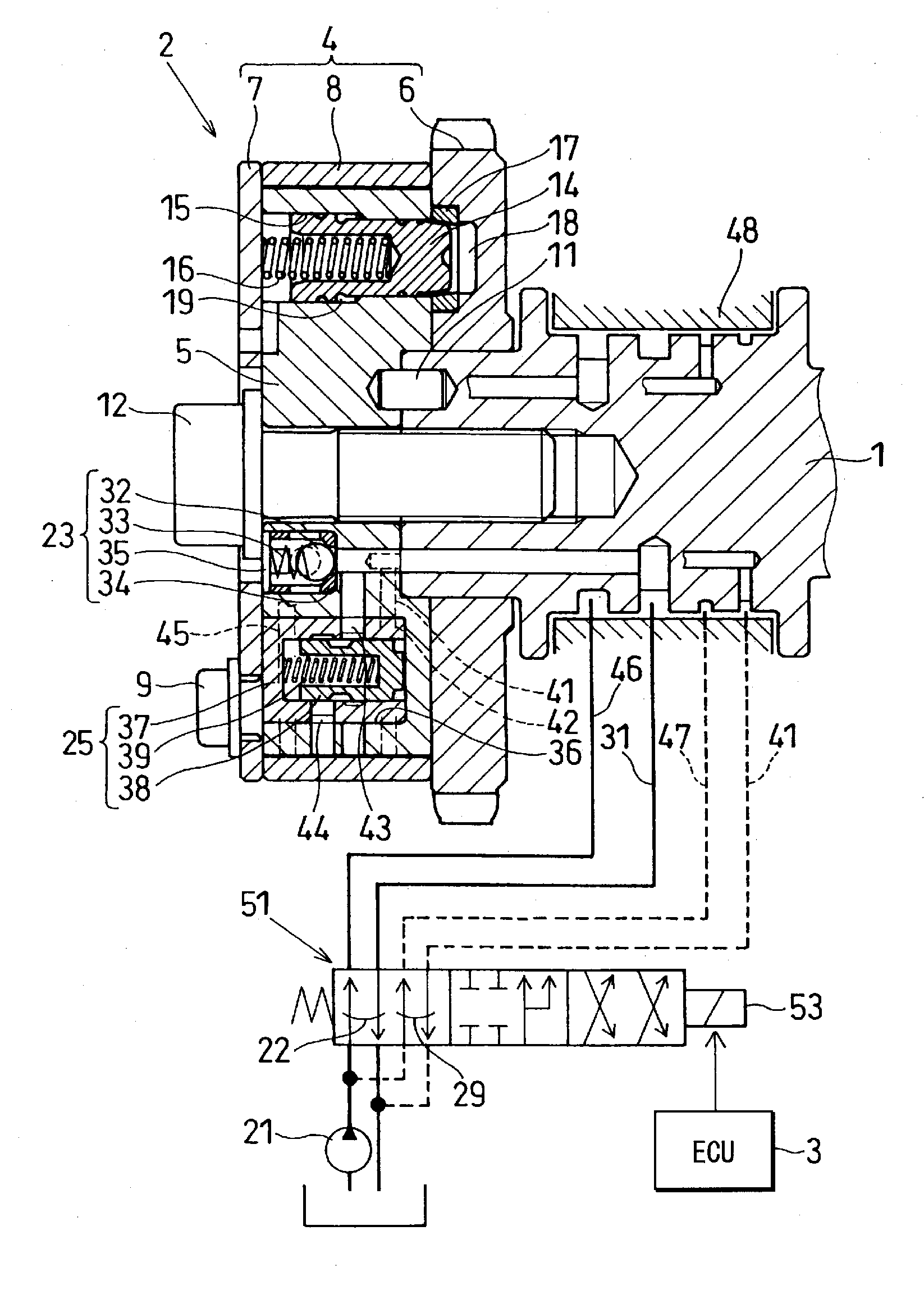
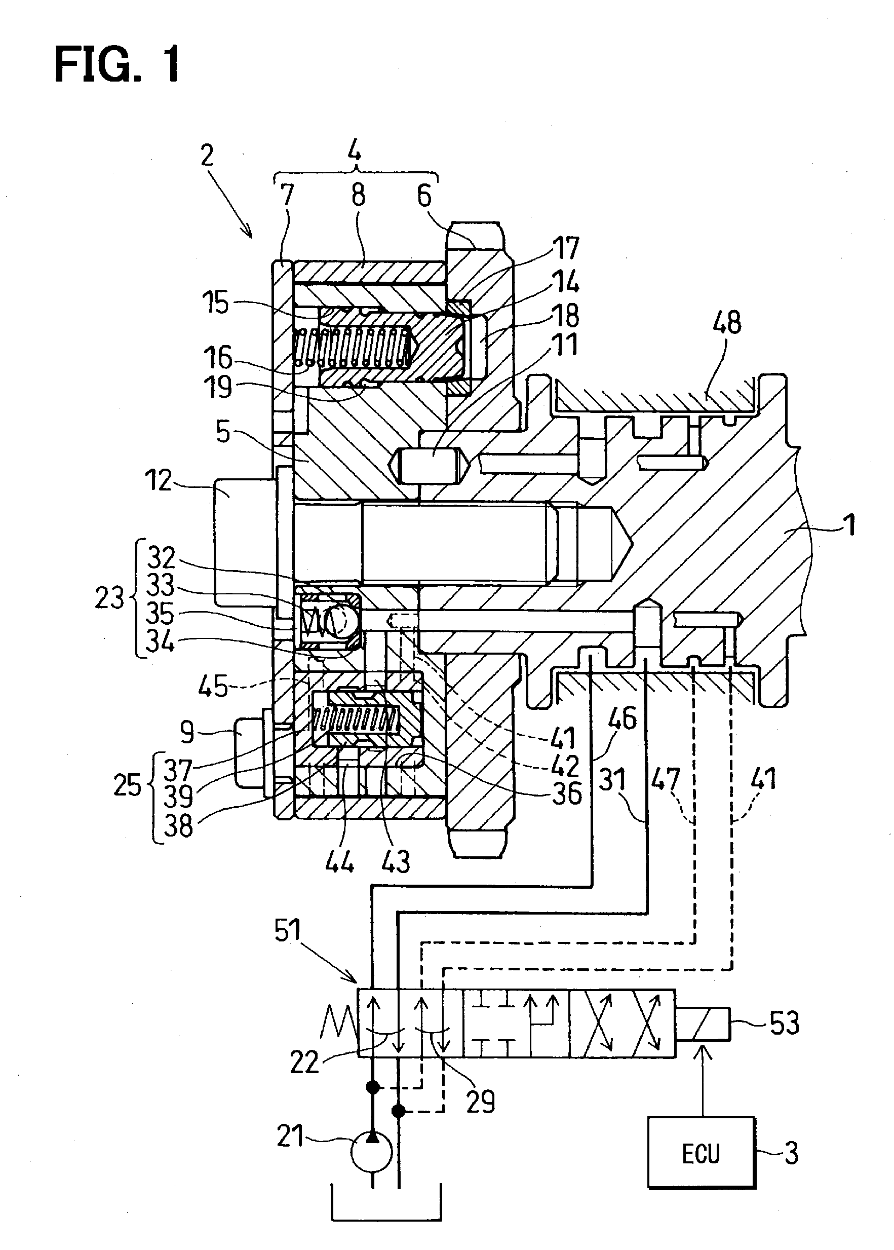
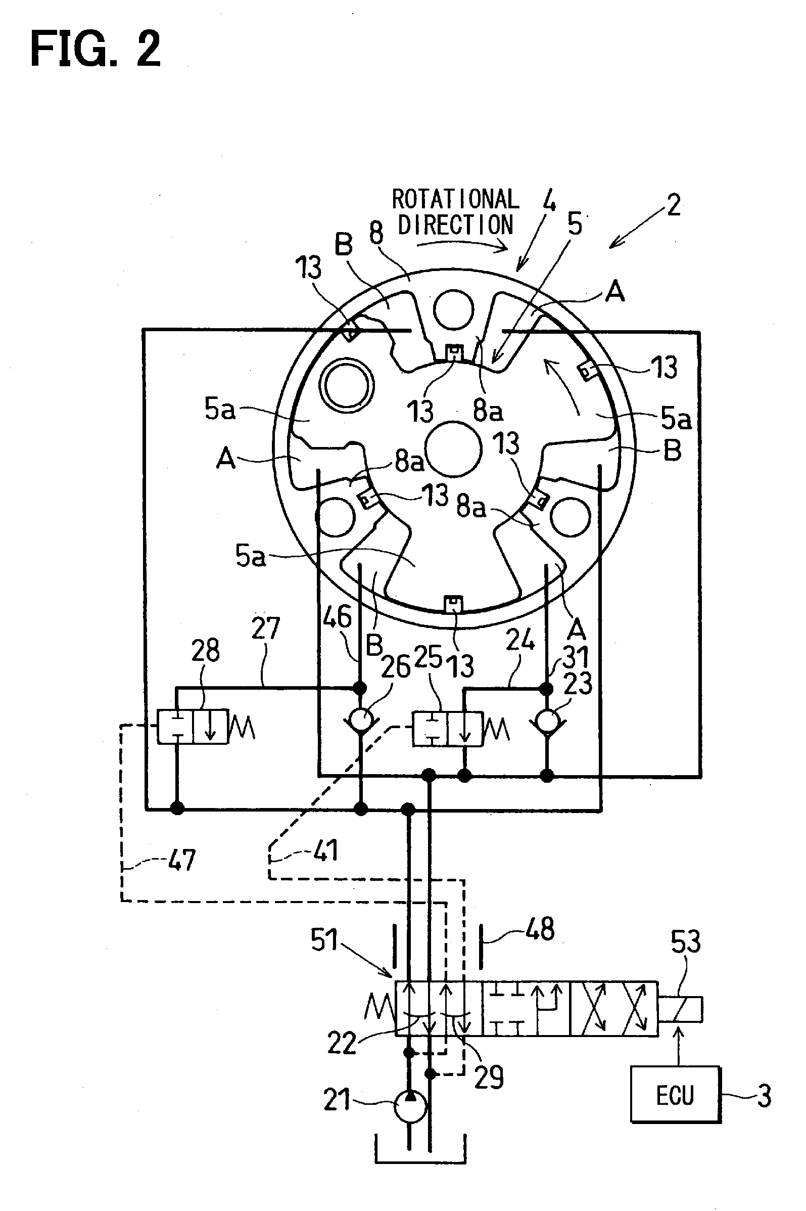
[0117]As described above, the VVT system of the first embodiment has the single solenoid spool valve 51, which includes both of the OCV 22 for supplying the drive hydraulic pressure to the advance chambers A or the retard chambers B and the OSV 29 for controlling the opening and closing of the advance and retard drain control valves 25, 28.

[0118]The OCV 22 and the OSV 29 therefore work with each other reliably and precisely, so that the reliability of a VVT system that includes two drain control valves 25, 28 is improved.

[0119]Being one solenoid spool valve 51, the OCV 22 and OSV 29 are mounted on the engine head or the like with fewer process steps, and take up less mounting space, so that mountability of the OCV 22 and the OSV 29 to the engine is improved.

[0120]Also, the number of components for the OCV 22 and the OSV 29 united as one solenoid spool valve 51 is fewer than separate OCV and OSV, so that the cost for providing these valves is reduced. Th...

second embodiment

[0134]A second embodiment of the present invention will be described with reference to FIGS. 6 and 7. In the following description, the components similar to those discussed in the first embodiment will be indicated by the similar reference numerals.

First Characteristic of Second Embodiment

[0135]The solenoid spool valve 51 of the first embodiment includes the first drain port 61 and the second drain port 65 as the drain ports for discharging the hydraulic fluid.

[0136]In contrast, the solenoid spool valve 51 of the second embodiment discharges the hydraulic fluid only from the first drain port 61. That is, in the second embodiment, only the one drain port for discharging the hydraulic fluid out of the solenoid spool valve 51 is shared.

[0137]Each drain system of the solenoid spool valve 51 of the second embodiment will now be described.

[0138]The advance chamber output port 62 can communicate with the axial drain port 69 through the third drain port 71, which radially extends through t...


PUM


Abstract

A phase control valve, which supplies a drive hydraulic pressure to an advance chamber or a retard chamber, is integrated with a drain switch valve, which controls opening and closing of an advance drain control valve and opening and closing of a retard drain control valve, to form a solenoid spool valve. The advance drain control valve is provided in an advance check valve bypass passage, which bypasses an advance check valve, and is driven by a pilot hydraulic pressure to open and close the advance check valve bypass passage. The retard drain control valve is provided in a retard check valve bypass passage, which bypasses a retard check valve, and is driven by a pilot hydraulic pressure to open and close the retard check valve bypass passage.

Description

CROSS REFERENCE TO RELATED APPLICATION[0001]This application is based on and incorporates herein by reference Japanese Patent Application No. 2006-250873 filed on Sep. 15, 2006.BACKGROUND OF THE INVENTION[0002]1. Field of the Invention[0003]The present invention relates to a valve timing control system for an internal combustion engine.[0004]2. Description of Related Art[0005]A previously proposed technique will be described with reference to FIG. 8 (some reference numerals used in FIG. 8 are common to those described in the following embodiments).[0006]Hereinafter, a valve timing control system, which changes opening and closing timing of at least one of an intake valve(s) and an exhaust valve(s) of an internal combustion engine, will be also referred to as a variable valve timing control system and will be denoted as a VVT system. A previously proposed VVT system shown in FIG. 8 includes a variable valve timing mechanism 2, a hydraulic control system and an electronic control unit...

Claims


Application Information

Patent Timeline
Patent Type & Authority Applications(United States)
IPC IPC(8): F16H53/04
CPCF01L1/022F01L1/024F01L1/3442F01L2001/34426Y10T74/2102F01L2001/34459F01L2001/34469F01L2101/00F01L2001/34433F01L2301/00
Inventor TAKAHASHI, KINYAUSHIDA, MASAYASUNOJIRI, TAKAOYAOKOU, SEIJIYAMADA, JUN
Owner DENSO CORP
Learn More