
High porosity thermally shock resistant ceramic structures

a ceramic structure and high porosity technology, applied in the field of ceramic honeycomb structures, can solve the problems of reducing the strength of the body, achieve the effects of high modulus of rupture strength, high degree of thermal shock resistance to the body, and high resistance to thermal shock damag

Active Publication Date: 2008-03-13
CORNING INC
View PDF7 Cites 16 Cited by
  • Summary
  • Abstract
  • Description
  • Claims
  • Application Information

AI Technical Summary

Benefits of technology

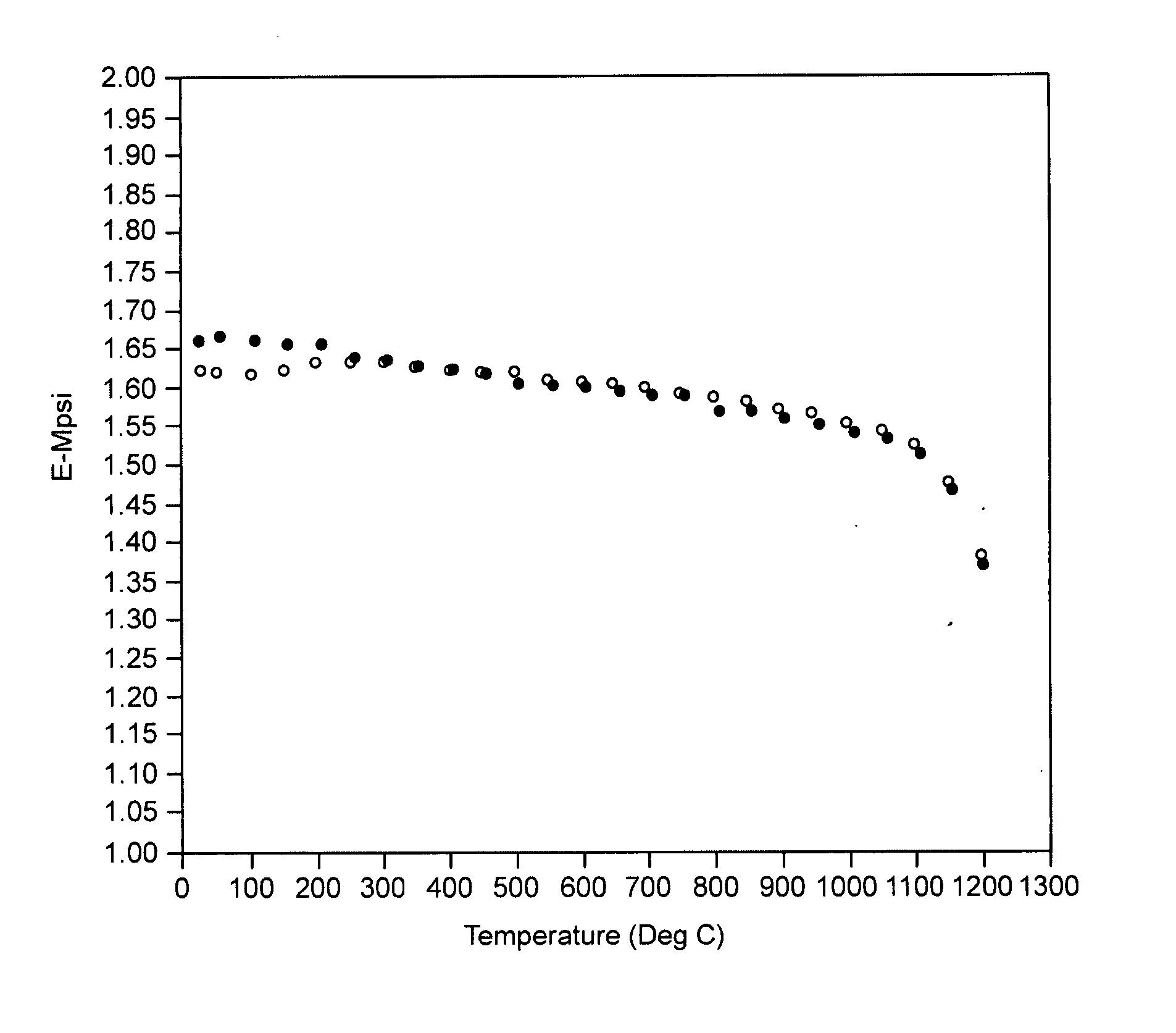
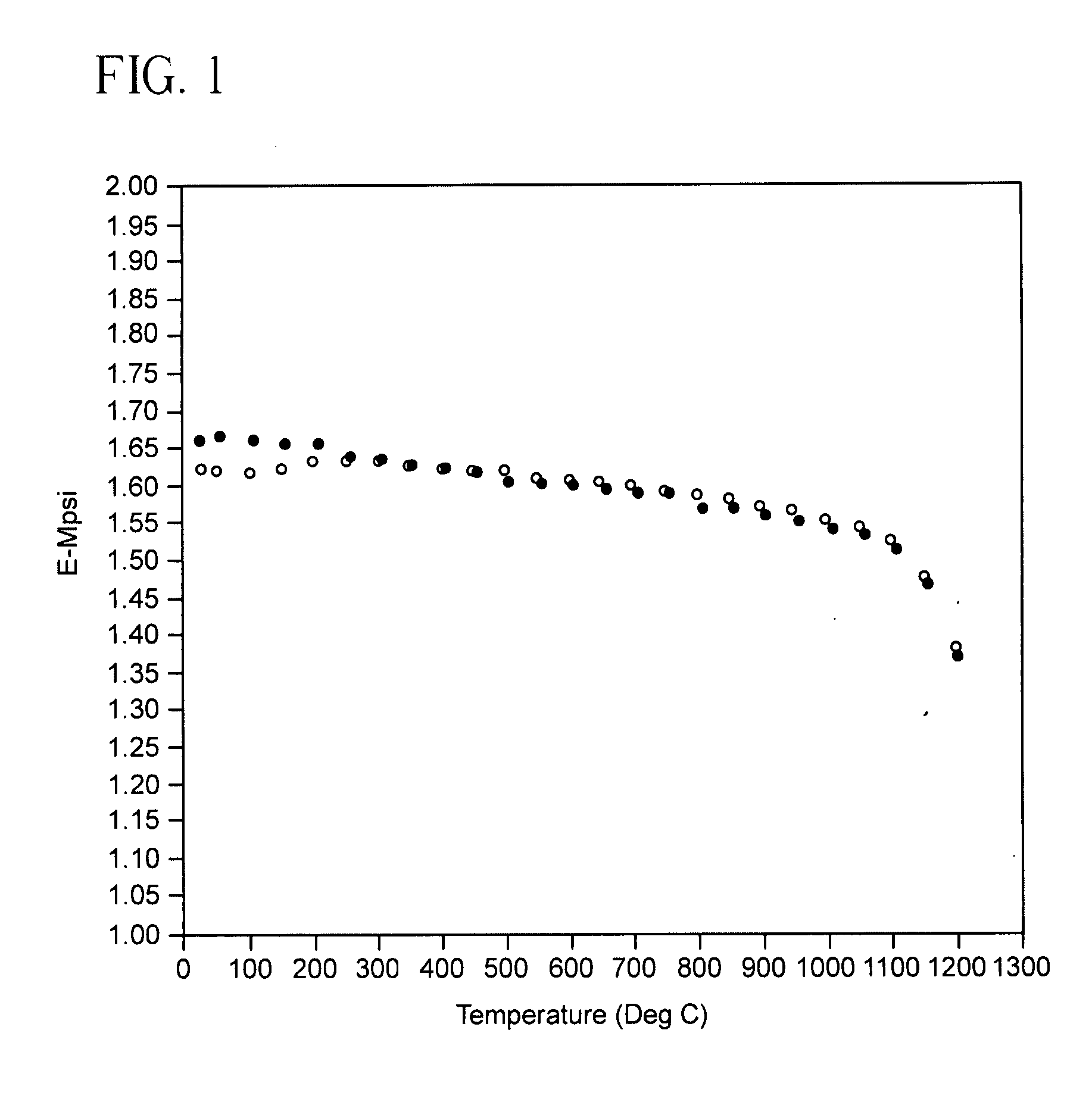
[0010] In accordance with the present invention, there is provided a composite ceramic body comprising a major first phase of a crystalline ceramic material and a minor second phase of material effective to modify the properties of the composite so that it retains a high modulus of rupture strength as well as a high resistance to thermal shock damage. The second or minor phase material imparts a higher degree of thermal shock resistance to the body by increasing the strain tolerance of the body at elevated temperatures, as compared with a body absent the second phase material. Thus the minor phase material makes the body more compliant at high temperatures, thereby reducing the stresses that arise in the presence of thermal gradients caused by rapid heating or cooling.
[0013] In yet another embodiment there is disclosed a ceramic honeycomb structure with a high thermal shock resistance comprising two or more constituent phases in the structure, wherein the major constituent phase is a microracked or a substantially non-microcracked ceramic, and wherein one of the minor constituent phases reduces the elastic modulus of the structure in the temperature range 600-1100° C., as compared to the room temperature value for the structure. The minor constituent phase that imparts increased thermal shock resistance to the honeycomb structure may be a glassy phase predominantly distributed at the grain boundaries of the major constituent phase, or it may be a glass-ceramic or ceramic phase that improves the high temperature compliance or strain tolerance of the structure and a total porosity (% P) of the structure is % P≧45%.

Problems solved by technology

One drawback is that the strength of the body is reduced by the presence of microcracks.

Method used


Image

  • High porosity thermally shock resistant ceramic structures
  • High porosity thermally shock resistant ceramic structures
  • High porosity thermally shock resistant ceramic structures

Examples


Embodiment Construction

[0019] In an important aspect, the present invention resides in the successful application of selected composite ceramic materials to applications for ceramic honeycomb filters and catalyst supports that require particularly high thermal shock resistance. These include honeycombs for diesel particulate filters (DPFs), for catalyzed diesel particulate filters, and for flow-through ceramic honeycomb catalyst supports located at points of rapid temperature change in engine exhaust treatment systems. The inventive composite ceramic materials that are effective for these applications comprise at least two identifiable ceramic or glassy phases that combine to provide composite ceramic bodies with improved modulus of rupture strength as well as improved thermal properties.

[0020] The first phase of the composite is a majority constituent thereof, i.e., the major phase of the ceramic, and is a crystalline ceramic phase of moderate to low thermal expansion. The second or minor phase may be a...


PUM

PropertyMeasurementUnit
Temperatureaaaaaaaaaa

Abstract

A thermally shock resistant ceramic body, such as a porous ceramic honeycomb structure for a wall flow diesel engine exhaust filter or a flow-through ceramic catalyst support, is formed of a composite ceramic material comprising a major first ceramic phase exhibiting good thermal shock resistance and a minor second phase material that substantially reduces the elastic modulus of the composite ceramic material at elevated temperatures.

Description

RELATED APPLICATIONS [0001] This application claims the benefit of, and priority to, U.S. Provisional Patent Application No. 60 / 840,767 filed Aug. 29, 2006 entitled ‘Thermally Shock Resistant Ceramic Structures,” the disclosure of which is hereby incorporated by reference herein.BACKGROUND OF THE INVENTION [0002] The present invention pertains to thermally shock resistant ceramics, and more particularly to a ceramic honeycomb structures such as ceramic catalyst supports or particulate filters having high thermal shock resistance, useful for example in thermally demanding applications such as motor vehicle exhaust gas catalyst supports and soot filters. [0003] Wall-flow diesel particulate filters (DPFs) and ceramic catalyst supports generally comprise thin-walled ceramic honeycomb structures with high geometric surfaces areas and, in some cases, with extensive interconnected porosity for good fluid filtration. Ceramic filters, in particular, must exhibit high mechanical strength for ...

Claims


Application Information

Patent Timeline
IPC IPC(8): B32B3/12B29C44/04
CPCC04B35/185Y10T428/24149C04B35/481C04B35/565C04B38/0006C04B2111/00793C04B2111/2084C04B2111/343C04B2235/36C04B2235/365C04B35/195C04B35/48C04B38/0074
Inventor BEALL, DOUGLAS MUNROEBEALL, GEORGE HALSEYMURTAGH, MARTIN JOSEPH
Owner CORNING INC
Learn More