Mold used for metal mold casting, and damper manufacturing method using the mold

a mold and metal mold technology, applied in the direction of foundry moulding equipment, instruments, foundry patterns, etc., can solve the problems of high material cost, high cost of metal molds, and high cost of corrosion protection treatment, so as to facilitate the subsequent cutting process, reduce vibration of housings, and improve filling performance

Inactive Publication Date: 2008-02-21
FUJITSU LTD
View PDF3 Cites 3 Cited by
  • Summary
  • Abstract
  • Description
  • Claims
  • Application Information

AI Technical Summary

Benefits of technology

[0019]A mold according to one aspect of the present invention used to manufacture, through metal mold casting, a damper that is fixed onto a housing in a disc drive and reduces a vibration of the housing, the disc drive recording information in and reproducing information from a recording medium includes a sectionally concave body that defines a shape of the damper, a first gate that introduces molten metal to the body from a runner, and is provided on a first side opposite to a concave of the body, and a second gate that introduces the molten metal to an overflow well from the body, and is provided at least one of a second side perpendicular to the first side, and a third side perpendicular to the second side and parallel to the first side. This mold removes a stagnant gas from the body through the outflow well. In addition, this mold limits the second gate to the second and / or the third sides that are likely to generate a stagnant gas instead of providing the second gate to the entire perimeter, improving the filling performance, and facilitating the subsequent cutting process. It is preferable that the second gate is provided in an approximately bilateral symmetry with respect to an axis perpendicular to the first side that halves the first side.
[0020]A thickness of each of the first and second gates is, for example, 2 mm or below, thereby facilitating the subsequent cutting process. The first gate may include three or more gates, and a central gate may be wider than each of the gates at both sides. The wide central gate weakens the pressure of the molten metal that collides with the center of the concave, and prevents a deformation of the concave, porosity, and misrum. In addition, the molten metal reaches both sides and the center of the concave almost at the same time, preventing a deformation, such as warping, and rough casting surface due to a molten metal cool-down time difference.
[0021]A method according to another aspect of the present invention for manufacturing a damper that is fixed onto a housing in a disc drive and reduces a vibration of the housing, the disc drive recording information in and reproducing the information from a recording medium, uses metal mold casting and the above mold. This manufacturing method exhibits a similar operation to the above mold. Molten metal of metal mold casting is, for example, zinc alloy, such as ZDC2, because zinc alloy has a low melting point, and can maintain the durability of the mold. The method may further include the step of surface-treating the cast, and omit the step of polishing the casting surface. The surface treatment protects corrosions, and prevents micro-dust from the casting surface. The well-controlled filling step enables the polishing step to be omitted, maintaining the economical efficiency. In addition, this configuration prevents peeling due to adhesion defects of the surface treatment, and a contamination of the disc drive and the clean room in which the damper is subsequently introduced, finally maintaining the manufacturing quality of the disc drive.
[0022]The disc drive manufacturing method according to another aspect of the present invention includes the step of fixing a damper manufactured by the above damper manufacturing method onto a housing, and mounting a recording medium and a head part that records information in and reproduces the information from the recording medium. Even when the mounting step is performed in the clean room, a contamination of the disc drive and the clean room can be prevented since there is no micro-dust from the casting surface of the damper, or no peeling due to good adhesion of the surface treatment. Thus, the manufacturing quality of the disc drive can be maintained.

Problems solved by technology

However, its material cost is high, and it needs a corrosion protection treatment.
However, in comparison with brass, iron expensively requires a thicker corrosion protection treatment.
On the other hand, stainless steel does not need a corrosion protection treatment, but its material cost is high and inferior in workability.
The magnetic disc drive needs to arrange a damper in the housing, but the housing has only a limited attachment space.
As for a stamping process, a large size and increased thickness would increase a stamping machine size and its comparatively large material margin causes a large material loss and the cost increase.
In addition, it is difficult for stamping to form a three-dimensional shape that has a thick part and a thin part on the one-body member.
Lost wax process is a self-extinguishing casting that destroys a die whenever the damper is manufactured, complex and takes a long process, and therefore expensive.
Forging, machining, sintering, resin injection molding, etc. are also conceivable but these methods have merits and demerits, such as a large working facility, a long cycle time, and a high material cost.
Brass has a specific gravity higher than zinc alloy but its melting point is so high that the durability is low and unsuitable for the mass production.
However, in reality, when a prototype of a damper is made of zinc alloy (ZDC2) through metal mold casting, generated gas from the molten metal and enclosed gas during molten metal filling process causes surface defects (rough casting surface), and the subsequent surface treatment suffers adhesion defects and peeling of painting and plating.
The degraded surface treatment, such as an exposure of casting surface and peeling due to adhesion defects, may contaminate the disc drive and the clean room, and resultantly affect the manufacturing quality of the disc drive.
However, the overflow gate provided to the entire perimeter of the mold as proposed by Kobayashi in manufacturing the damper increases a material waste, takes time to fill the molten metal in the mold, and causes porosity and misrum.
In addition, Kobayashi increases the cutting force in the cutting process that separates gates from a cast, a size of the cutting machine, and the cost.

Method used


Image

  • Mold used for metal mold casting, and damper manufacturing method using the mold
  • Mold used for metal mold casting, and damper manufacturing method using the mold
  • Mold used for metal mold casting, and damper manufacturing method using the mold

Examples


Embodiment Construction

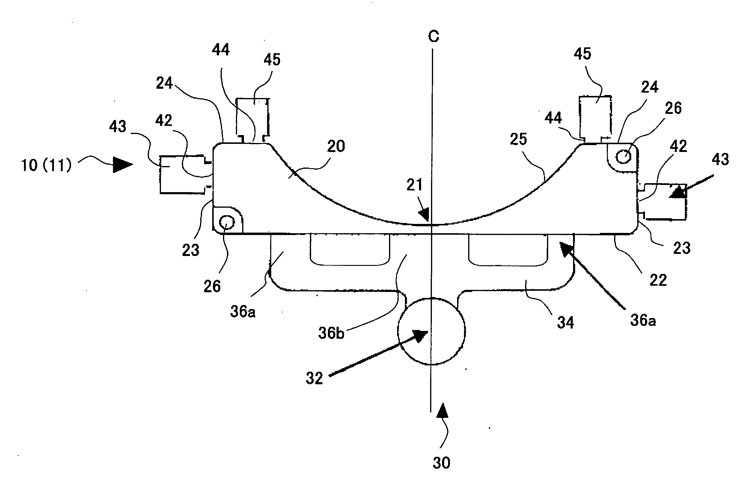
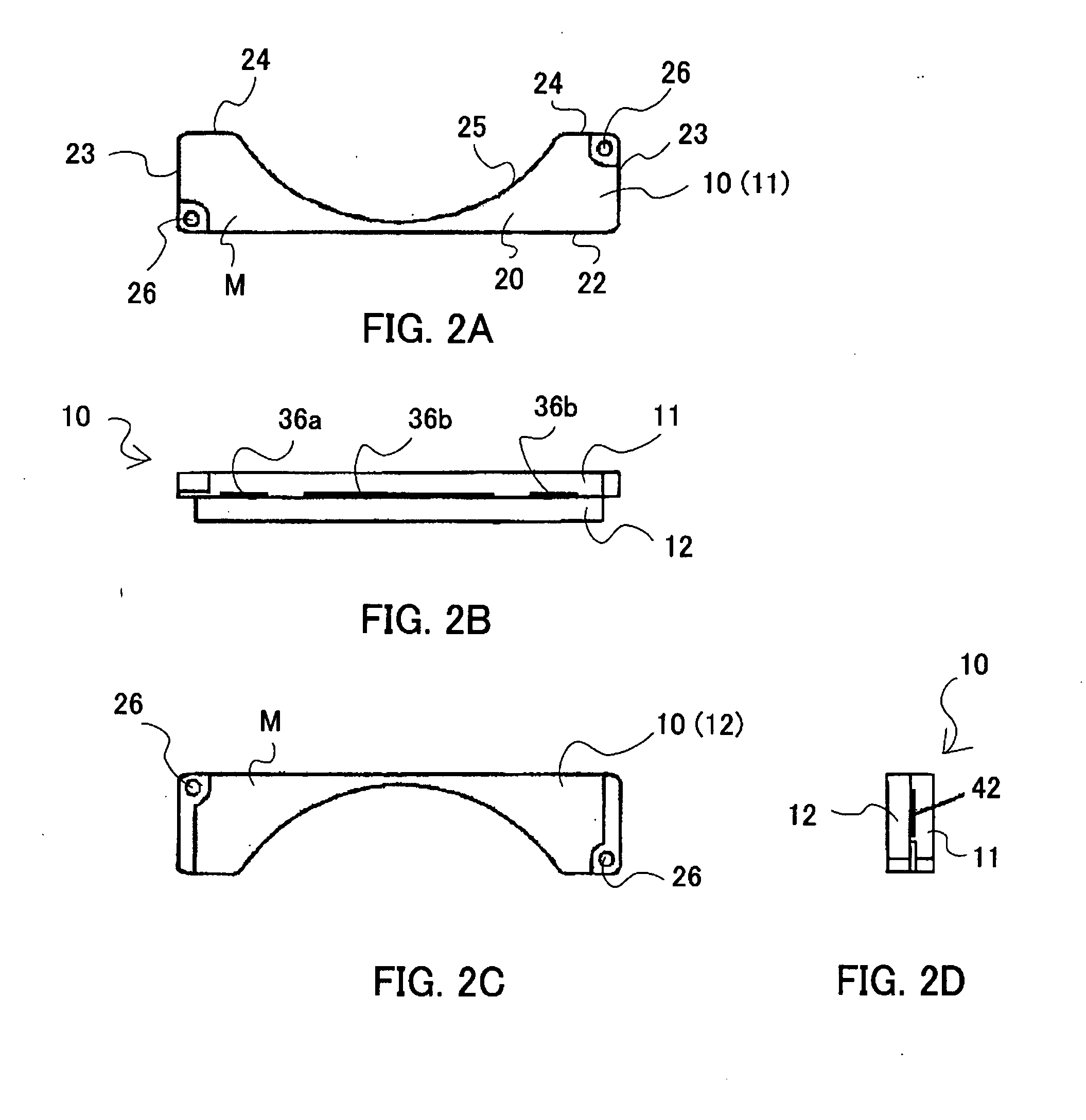
[0031]Referring now to the accompanying drawings, a description will be given of a method for manufacturing a damper (or weight) through metal mold casting including die casting. Referring now to FIGS. 1 to 2D, a description of a mold (or die) 10 used for metal mold casting will be given. Here, FIG. 1 is a schematic plane view of a movable mold (or die) 11 of the mold 10, but omits an ejector pin. FIG. 1 may be recognized as a schematic plane view of a cast with metal injecting part and over-flow wells right after molten metal cools down and solidifies. FIGS. 2A to 2D are schematic views of a mold (or die) 10. The mold 10 is fixed on a hot chamber casting machine. However, the present invention is not limited to a type of a casting machine, a cold chamber casting machine or another casting machine may be used.

[0032]The mold 10 includes the movable mold 11 and the stationary mold 12, and the movable mold 11 moves relative to the stationary mold 12. The movable mold 11 includes, as sh...


PUM

PropertyMeasurementUnit
specific gravityaaaaaaaaaa

Abstract

A mold used to manufacture, through metal mold casting, a damper that is fixed onto a housing in a disc drive and reduces a vibration of the housing, the disc drive recording information in and reproducing information from a recording medium. The mold includes a sectionally concave body that defines a shape of the damper, a first gate that introduces molten metal to the body from a runner, and is provided on a first side opposite to a concave of the body, and a second gate that introduces the molten metal to an overflow well from the body, and is provided at least one of a second side perpendicular to the first side, and a third side perpendicular to the second side and parallel to the first side.

Description

[0001]This application claims a foreign priority based on Japanese Patent Application No. 2006-175443, filed on Jun. 26, 2006, which is hereby incorporated by reference herein in its entirety as if fully set forth herein.BACKGROUND OF THE INVENTION[0002]The present invention relates generally to a mold used to manufacture a member formed through metal mold casting, and a manufacturing method of the member. The present invention also relates to a damper manufacturing mold, and more particularly to a damper manufacturing method that uses metal mold casting. The present invention is suitable, for example, for a manufacture of a damper used for a hard disc drive (“HDD”). Although a description will now be given of a damper as the member for the HDD, the present invention is also applicable to another member.[0003]Along with the recent widespread Internet, etc., providing of an inexpensive magnetic disc drive that records a large amount of information including still and motion pictures ...

Claims


Application Information

Patent Timeline
Patent Type & Authority Applications(United States)
IPC IPC(8): G11B3/61
CPCB22C9/06B22C9/22Y10T29/49025G11B33/08F16F7/10
Inventor UEDA, MASANORISUWA, MASAYA
Owner FUJITSU LTD
Why Eureka
Try Eureka