Ac/Dc Converter Comprising Plural Converters in Cascade

a technology of ac/dc converter and cascade, which is applied in the direction of electric variable regulation, process and machine control, instruments, etc., can solve the problems of affecting the operation of the converter. , to achieve the effect of reducing emi, improving utilization of the transformer, and reducing ringing

Active Publication Date: 2008-02-07
TEXAS INSTR INC
View PDF7 Cites 51 Cited by
  • Summary
  • Abstract
  • Description
  • Claims
  • Application Information

AI Technical Summary

Benefits of technology

[0008] By having such a converter, it is possible to provide a converter that is efficient across a wide range of different input voltages. The tracking boost converter will operate to provide a voltage across the bulk capacitor approximately proportional to the input voltage. This voltage across the bulk capacitor is then used by the buck converter to provide the input to the output isolation transformer. By having the feedback control from the output, the converter will be able to operate the isolation transformer stage with a fixed voltage ratio and the buck converter can adapt the voltage received from the bulk capacitor to give a quasi-fixed input voltage to the isolation transformer. This will result in a highly efficient controller across the range of input voltages.
[0023] In one embodiment of the invention there is provided an AC / DC converter in which the bulk capacitor voltage is adapted to provide an output DC voltage approximately proportional to the input AC voltage so that at low input line AC and low output line DC voltages in the order of 200V, the inductance of the input choke of the pre-regulator boost converter stage is so chosen that the boost converter operates in continuous mode and at a high input line AC voltage and high output DC voltages of the order of 400V operates in discontinuous mode. The inductance value of the input choke will affect the manner in which the controller operates the boost converter. By choosing an appropriate value of inductance, the controller will vary the duty cycle appropriately so that the converter operates the boost converter in discontinuous mode at high voltage. This will help to overcome the losses associated with the reverse recovery properties of the boost diode. Furthermore, by choosing the appropriate value of inductance, the controller can operate the boost converter in continuous mode at higher loads at low voltages without significant conduction losses.

Problems solved by technology

There are however problems associated with the known types of AC / DC converters.
First of all, many of these converters experience problems with the filtering of electromagnetic interference (EMI) caused by the operation of the converter.
Every switching stage of the converter generates interference.
Modern power converters operate with switching at a frequency typically in the range of 20 KHz to 1 MHz or higher, and such switching can generate significant interference to other electrical equipment.
Particular challenges in this area lie in filtering the current ripple in the input boost choke or flyback stage as typically used in power-factor correction stages and also in limiting the common-mode noise generated in the isolation transformer between the line / mains and the electronic circuitry being fed by the supply.
The other main design problem associated with the known types of AC / DC converters concerns the efficiency of the converters.
In particular, there is a design challenge in getting optimum efficiency from power converters across the wide range of input voltages, where the input voltage cycle peak varies from typically 1.414*85V to 1.414*265V depending on the country.
Design of AC / DC converters with an approximately fixed value of bulk capacitor voltage typically involves compromises in optimising efficiency across the differing line voltages.
However, there are various problems with these types of converters including those outlined above.

Method used


Image

  • Ac/Dc Converter Comprising Plural Converters in Cascade
  • Ac/Dc Converter Comprising Plural Converters in Cascade
  • Ac/Dc Converter Comprising Plural Converters in Cascade

Examples


Embodiment Construction

[0029] The invention will be more clearly understood from the following description of some embodiments thereof, given by way of example only, with reference to the accompanying drawings, in which:

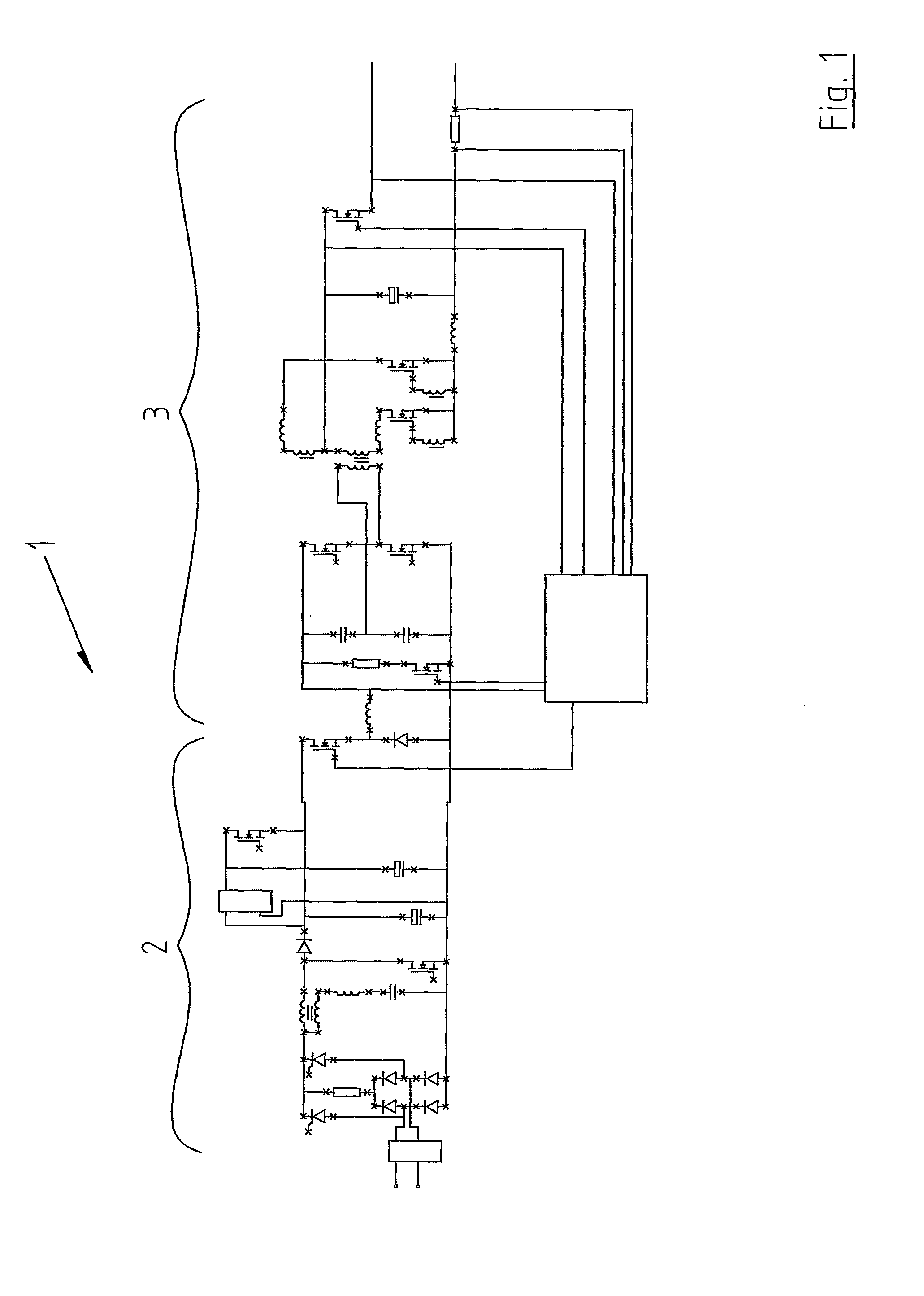
[0030]FIG. 1 is a circuit diagram view of an AC / DC converter in accordance with the invention,

[0031]FIG. 2 is an enlarged view of portion of FIG. 1 showing the AC / DC conversion stage of the AC / DC converter,

[0032]FIG. 3 is an enlarged view of portion of FIG. 1 showing the DC / DC conversion stage of the AC / DC converter,

[0033]FIG. 4 is a circuit diagram of a full duty transformer stage in accordance with the invention, and

[0034]FIG. 5 is a circuit diagram of a multiple output winding configuration for a transformer used in accordance with the invention.

[0035] Referring to the drawings and initially to FIGS. 1 to 3 thereof, there is provided an AG / DC converter, indicated generally by the reference numeral 1, having an AC / DC conversion stage 2 comprising a dual mode input stage and a DC / DC ...


PUM


Abstract

The present invention relates to an AC / DC converter (1) of the type having an AC / DC conversion stage (2) and a DC / DC conversion stage (3), the AC / DC conversion stage (2) comprising an input filter stage (4), an input rectifier stage (5) and a tracking boost converter stage. The boost converter stage in turn comprises an input choke (10), a boost diode (16) and a bulk capacitor (17). The bulk capacitor (17) is arranged to store a range of voltages substantially proportional to the input voltage of the converter. The DC / DC stage (3) is arranged to receive the range of voltages from the bulk capacitor (17) and is controllable to provide a desired DC output regardless of the voltage received from the bulk capacitor (17). This is achieved through careful combination of components and use of output feedback control to control the voltage applied to an isolated transformer (41) in the DC / DC stage.

Description

INTRODUCTION [0001] The present invention relates to an AC / DC converter of the type comprising an AC / DC conversion stage and a DCIDC conversion stage, the AC / DC conversion stage comprising a dual mode input stage having an input filter and an input rectification circuit, the AC / DC conversion stage further comprising a pre-regulator tracking boost converter stage having an input boost choke, a boost diode and a bulk capacitor, the bulk capacitor being capable of storing a range of DC voltages thereon substantially proportional to the input AC voltage. [0002] AC / DC converters have been known for many years and are used extensively particularly throughout the electronics industry. These converters take power from a utility line or mains supply and deliver a predetermined DC output, typically at the lower voltages required by electronic circuitry as used in industrial, communications, computing, medical and general applications. Typically, an AC / DC converter comprises a pre-regulator wh...

Claims


Application Information

Patent Timeline
IPC IPC(8): H02M3/335H02H9/00H02M1/00H02M1/42H02M3/337H02M7/12
CPCH02M1/4225H02M3/33569Y02B70/126H02M7/125H02M3/3376Y02B70/10H02M3/33571H02M1/0085
Inventor YOUNG, GEORGE
Owner TEXAS INSTR INC
Why Eureka
Try Eureka