
Heatsink Apparatus for Applying a Specified Compressive Force to an Integrated Circuit Device

a heat dissipation device and integrated circuit technology, applied in the direction of cooling/ventilation/heating modification, semiconductor device details, semiconductor/solid-state device details, etc., can solve the problems of ic performance suffer, electrical stability at the contact interface of the package and the circuit board may be compromised, and part or completely non-functioning i

Active Publication Date: 2008-01-31
IBM CORP
View PDF51 Cites 39 Cited by
  • Summary
  • Abstract
  • Description
  • Claims
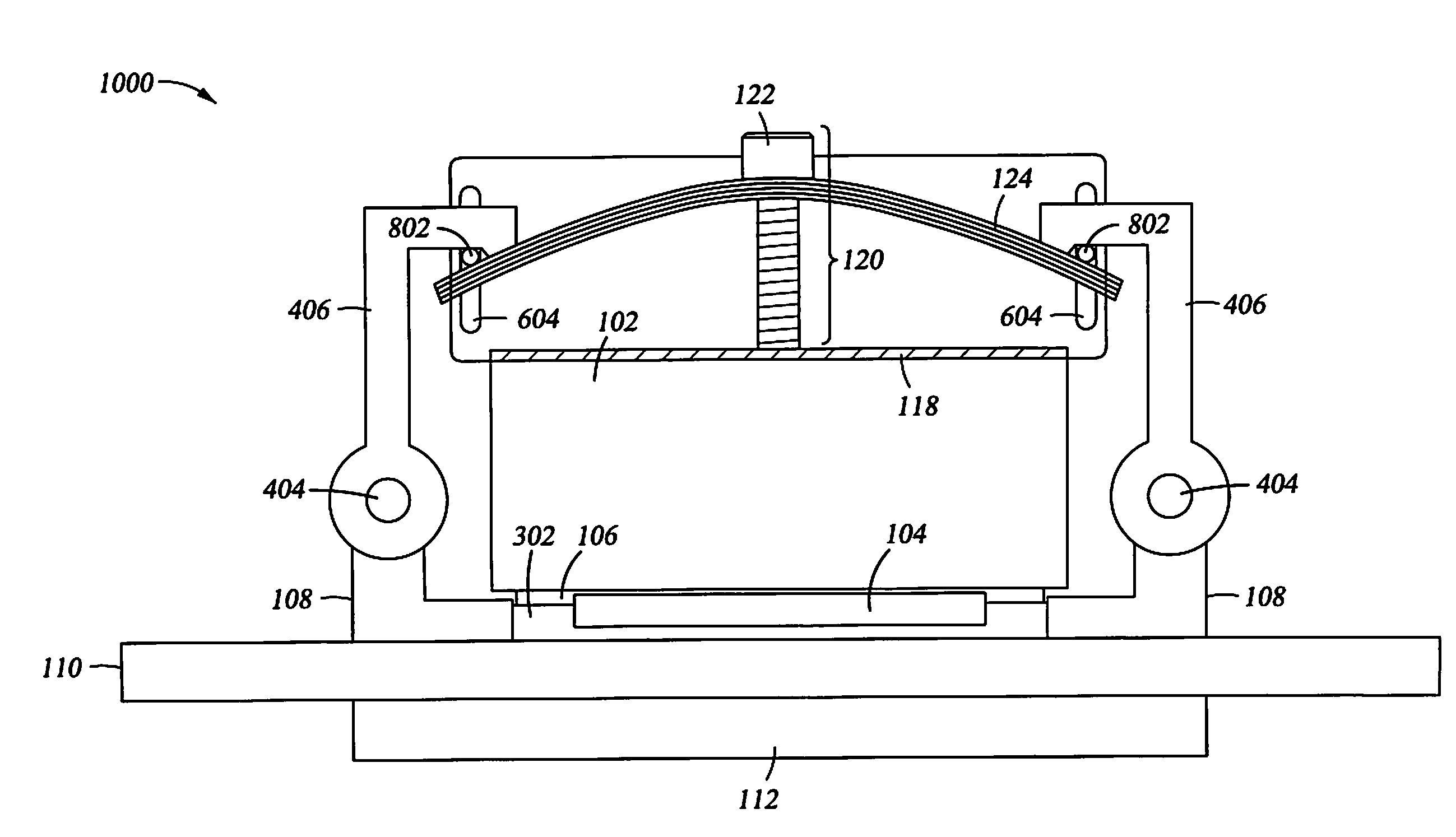
  • Application Information

AI Technical Summary

Benefits of technology

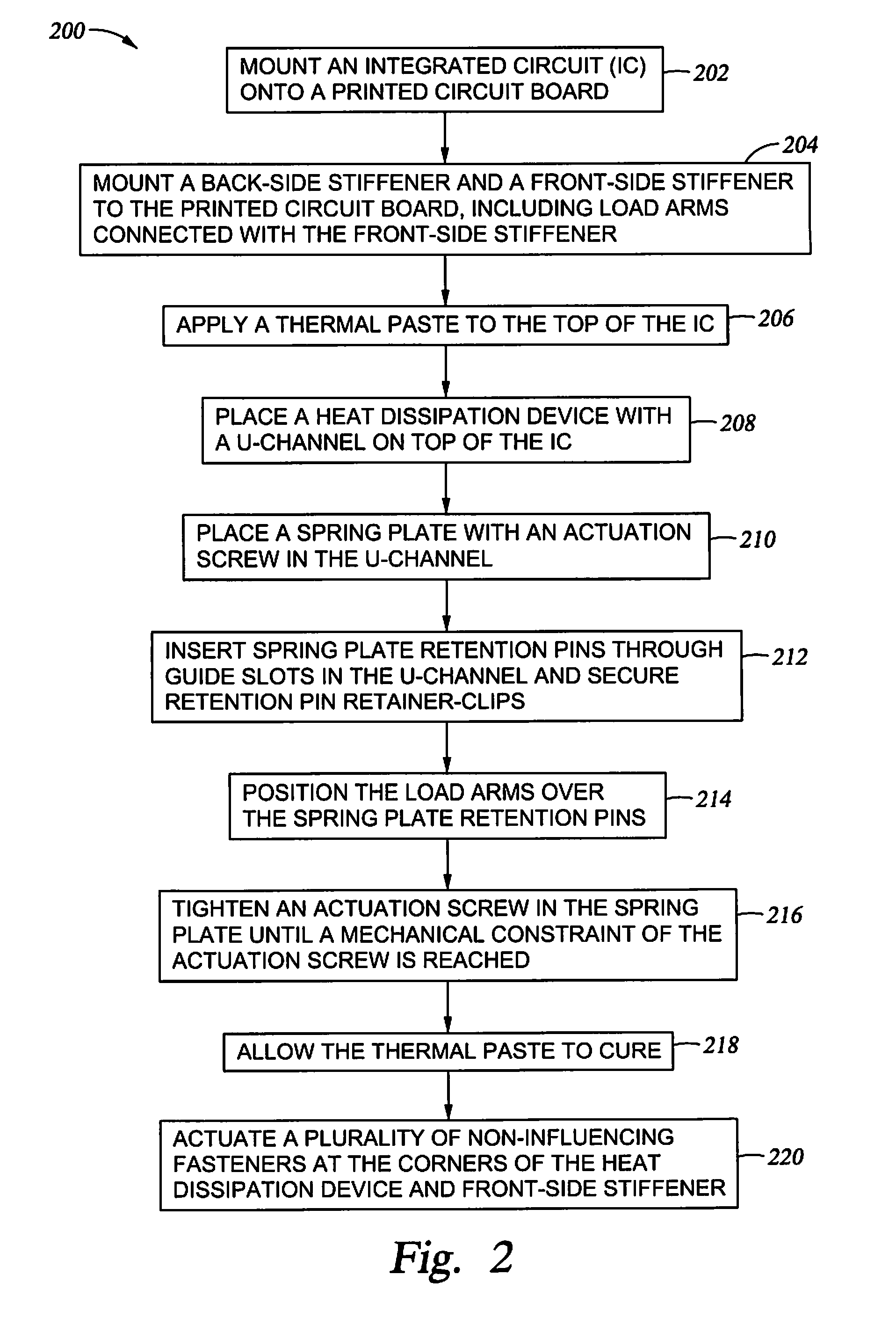
[0009]The present invention generally relates to heat dissipation in a computing device, and more specifically, to a method and apparatus for applying a specified compressive force by a heat dissipation device for an integrated circuit. In one embodiment, a method for applying a specific compressive force from a heat dissipation device onto one or more integrated circuit devices includes placing the integrated circuit device onto a printed circuit board (PCB) and then placing the heat dissipation device onto the integrated circuit device. The method further includes tightening an actuation screw in a spring plate against a portion of the heat dissipation device. The actuation screw may be prevented from being tightened beyond a mechanical constraint corresponding to a pre-set calibration for the specific compressive force.
[0010]In one embodiment, a device for applying a specific compressive force from a heat dissipation device onto one or more integrated circuit devices is given. The device may include an integrated circuit placed on a PCB, the heat dissipation device placed on the integrated circuit and a spring plate placed on the heat dissipation device. The device may further include an actuation screw threaded through the spring plate. The actuation screw may be configured so that when it is tightened, the actuation screw may cause a compressive force to be applied from the heat dissipation device onto the one or more integrated circuit devices. The actuation screw may be prevented from being tightened beyond a mechanical constraint corresponding to a pre-set calibration for the specific compressive force.
[0011]In one embodiment, a method for manufacturing an assembly including a heat dissipation device, a spring plate, and a spring rod assembly may include determining a first minimum specific compressive force to be applied to an integrated circuit device by the assembly when an actuation screw is tightened through the spring plate. The method may also include determining a corresponding second minimum specific compressive force to be applied to the heat dissipation device, resulting in the first minimum specific compressive force being applied to the integrated circuit device. The method may further include calculating a first deflection distance for at least one of the spring plate and the spring rod assembly such that the at least one of the spring plate and the spring rod assembly are collectively deflected by the first deflection distance when at least the second minimum specific compressive force is applied to the heat dissipation device. The method may further include providing the actuation screw with a thread pattern and a mechanical constraint which, when tightened, may produce a second deflection distance for the spring plate. The actuation screw may be mechanically prevented from being tightened to a position where the second deflection distance is greater than the first deflection distance.

Problems solved by technology

When the IC becomes too hot, damage to the IC circuitry may occur, resulting in a partially or completely non-functioning IC.
However, similar to other packaging techniques, LGA packaging may require a specified compressive force to hold the IC package in place.
If an IC package is not held in place by an adequate compressive force, the electrical stability at the contact interface of the package and circuit board may be compromised and IC performance may suffer.
If the IC package is held in place with a compressive force greater than what is necessary, there may be a risk of mechanical damage to the IC and / or a possibility of electrical shorting.

Method used


Image

  • Heatsink Apparatus for Applying a Specified Compressive Force to an Integrated Circuit Device
  • Heatsink Apparatus for Applying a Specified Compressive Force to an Integrated Circuit Device
  • Heatsink Apparatus for Applying a Specified Compressive Force to an Integrated Circuit Device

Examples


Embodiment Construction

[0027]The present invention generally relates to heat dissipation in a computing device, and more specifically, to a method and apparatus for applying a specified compressive force by a heat dissipation device for an integrated circuit. In one embodiment, a method for applying a specific compressive force from a heat dissipation device onto one or more integrated circuit devices includes placing the integrated circuit device onto a printed circuit board (PCB) and then placing the heat dissipation device onto the integrated circuit device. The method further includes tightening an actuation screw threaded through a spring plate against a portion of the heat dissipation device. The actuation screw may be prevented from being tightened beyond a mechanical constraint corresponding to a pre-set calibration for the specific compressive force.

[0028]In the following, reference is made to embodiments of the invention. However, it should be understood that the invention is not limited to spec...


PUM


Abstract

A method and apparatus for applying a specified compressive force by a heat dissipation device for an integrated circuit are given, including placing the integrated circuit device onto a printed circuit board and then placing the heat dissipation device onto the integrated circuit device. The method includes tightening an actuation screw in a spring plate against a portion of the heat dissipation device. The actuation screw may be prevented from being tightened beyond a mechanical constraint corresponding to a pre-set calibration for the specific compressive force, which may be greater than or equal to a minimum compressive force corresponding to the greater of a minimum thermal interface pressure and a minimum contact interface pressure. Additionally, the specific compressive force may be less than or equal to a maximum pressure which may be exerted on the integrated circuit device.

Description

CROSS-REFERENCE TO RELATED APPLICATIONS[0001]This application is related to U.S. patent application Ser. No. 11 / 201,972, Attorney Docket No. ROC920050088US1, entitled METHOD AND APPARATUS FOR MOUNTING A HEAT SINK IN THERMAL CONTACT WITH AN ELECTRONIC COMPONENT, filed Aug. 11, 2005, by John Lee Colbert et al. This related patent application is herein incorporated by reference in its entirety.BACKGROUND OF THE INVENTION[0002]1. Field of the Invention[0003]The present invention generally relates to heat dissipation for a computing device, and more specifically, to a method and apparatus for applying a specified compressive force by a heat dissipation device for an integrated circuit.[0004]2. Description of the Related Art[0005]Modern computer processors are typically integrated circuits (IC) which are fabricated upon a die and placed in a package. As IC's become faster, smaller, and generally more powerful, they may also generate more heat. When the IC becomes too hot, damage to the IC...

Claims


Application Information

Patent Timeline
IPC IPC(8): H05K7/20
CPCH01L23/4093H01L2924/0002H01L2924/00H01L23/40
Inventor COLBERT, JOHN L.CORBIN, JOHN S.EAGLE, JASON R.HAMILTON, ROGER DUANEMIKHAIL, AMANDA E.SINHA, ARVIND K.SOBOTTA, TERRY L.
Owner IBM CORP
Learn More