
Method for manufacturing piezoelectric resonator

a piezoelectric resonator and manufacturing method technology, applied in the field of piezoelectric resonators, can solve problems such as yield reduction, and achieve the effects of low etching rate, high accuracy, and easy adjustment of frequency rang

Inactive Publication Date: 2008-01-24
NIHON DEMPA KOGYO CO LTD
View PDF1 Cites 3 Cited by
  • Summary
  • Abstract
  • Description
  • Claims
  • Application Information

AI Technical Summary

Benefits of technology

[0014] The present invention is achieved under the consideration of such a circumstance and its object is to provide a method for manufacturing a piezoelectric resonator which can perform frequency matching with high reliability when conducting rough frequency adjustment by adjusting the shape formation of a piezoelectric oscillating piece before forming an electrode film so that the reduction in the yields can be prevented.
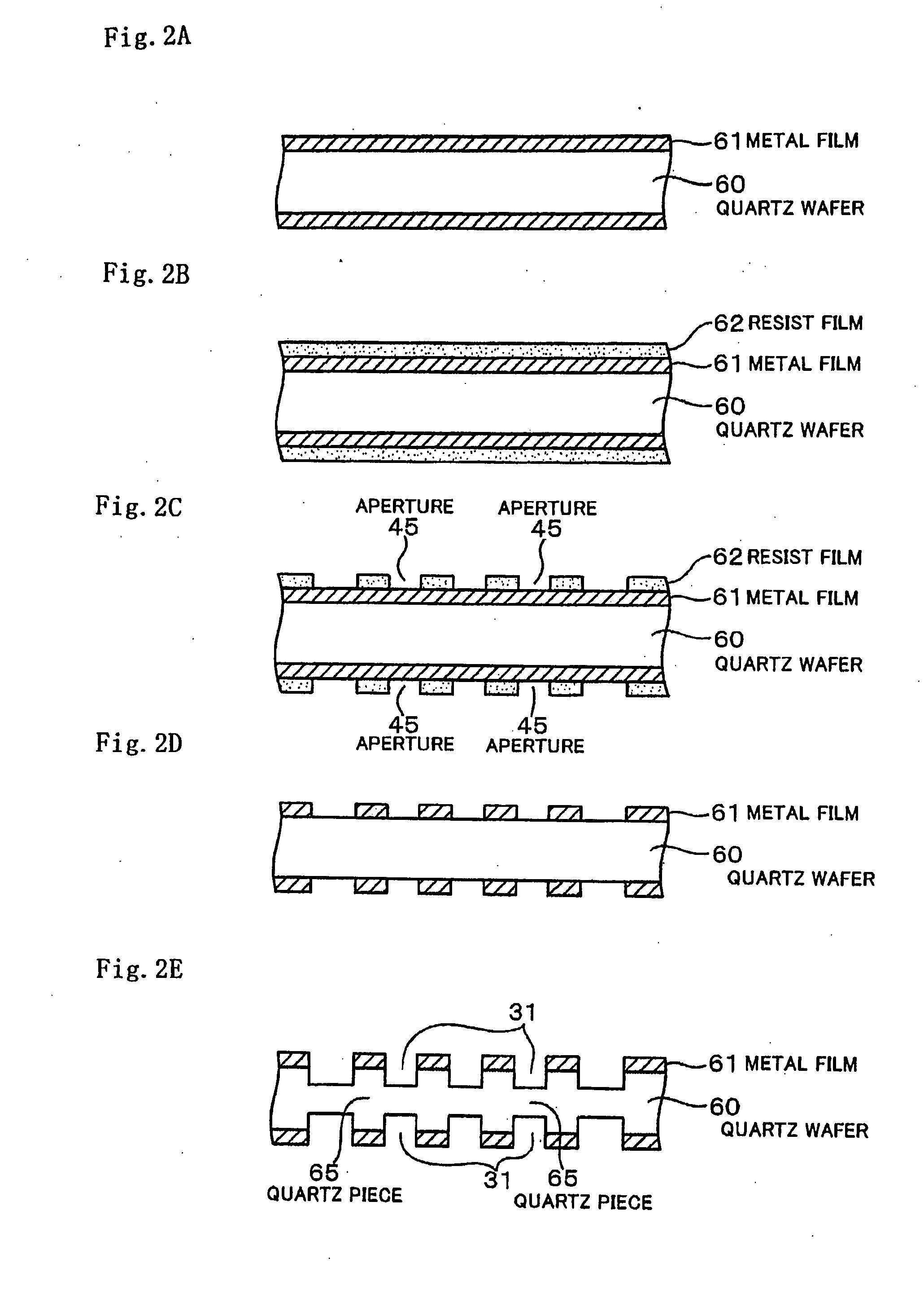
[0033] According to the present invention, etching to form the outside shape of the piezoelectric oscillating piece and etching to form the grooves are conducted simultaneously, and after forming the groove, the shape formation of the piezoelectric oscillating piece is started again from the same depth as the grooves under the condition of covering the grooves with the metal film. After the outside shape is formed, matching of frequency is conducted by etching the side surface of the piezoelectric oscillating piece in succession. Therefore, the matching of frequency can be performed by processing only the side surface of the piezoelectric oscillating piece. Accordingly, is compared with the usual practice of conducting the frequency matching by processing the side surface of the piezoelectric oscillating piece and processing the grooves formed in the vibrating arms at the same time, the rough frequency adjustment can be achieved at a low etching rate. Therefore, it is possible to perform the frequency matching without undue difficulty and with high accuracy. This makes it possible to get the piezoelectric oscillating piece which has an easily adjustable range of frequency with high reliability when conducting the fine frequency adjustment after forming the electrode pattern later.

Problems solved by technology

Therefore, it has a problem that fine frequency adjustment doesn't go well even through the frequency adjustment process after the electrode pattern forming process, which reduces yields.

Method used


Image

  • Method for manufacturing piezoelectric resonator
  • Method for manufacturing piezoelectric resonator
  • Method for manufacturing piezoelectric resonator

Examples


Embodiment Construction

)

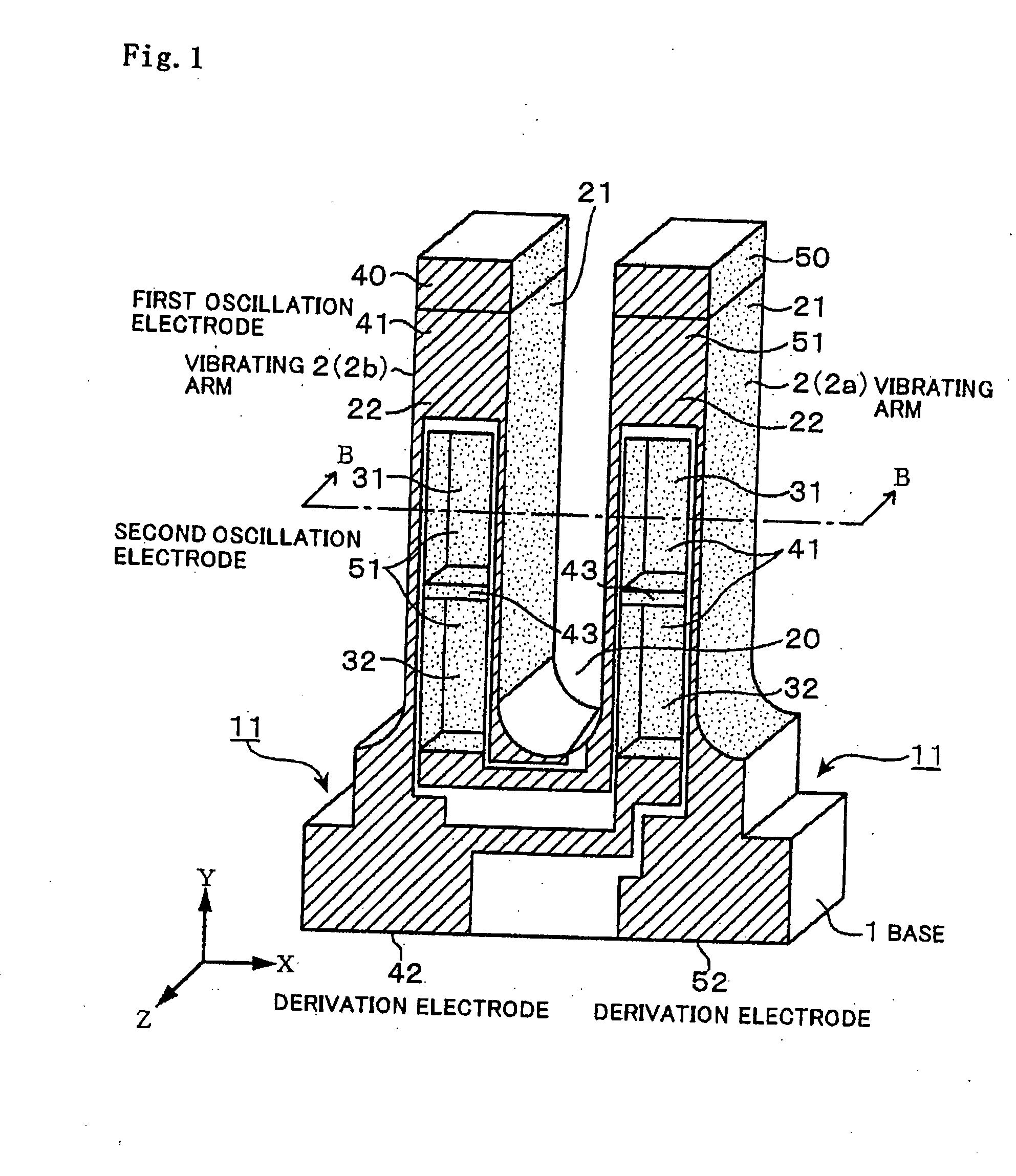
[0043] A method for manufacturing a tuning fork type quartz resonator which is a piezoelectric resonator will be explained as an embodiment of the present invention. Since the structure of the quartz resonator relating to the present embodiment is the same as that of the quartz resonator explained in the article of Related Art with reference to FIG. 7, explanation of the same portions will be omitted.

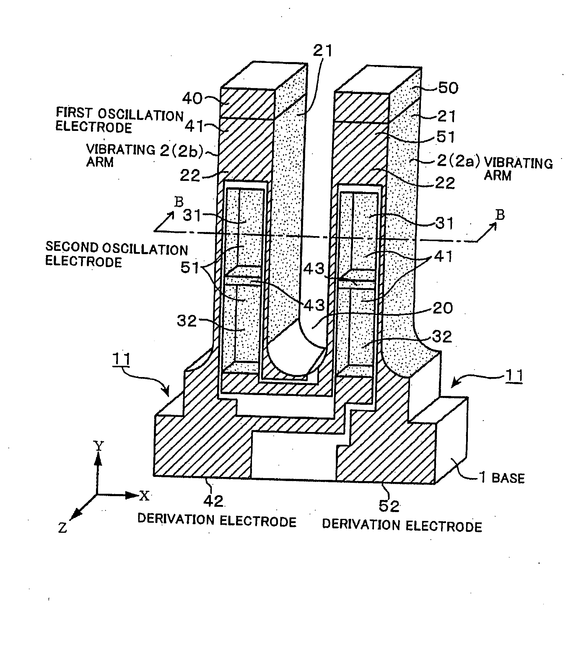
[0044] As shown in FIG. 1, a first excitation electrode 41 is formed on the whole inner surfaces of a plurality of grooves aligned in the longitudinal direction of an vibrating arm 2a, for instance, a first groove 31 and a second groove 32, and between these grooves 31 and 32 on the vibrating arm 2a out of the vibrating arms 2. That is, by the excitation electrode 41 formed on a so-called bridge portion 43 corresponding to a portion between the first groove 31 and the second groove 32, the excitation electrodes 41 within the respective grooves 31 and 32 of the vibrating arm 2a are con...


PUM

PropertyMeasurementUnit
Frequencyaaaaaaaaaa

Abstract

To provide a method for manufacturing a piezoelectric resonator which can conduct frequency matching with high reliability when performing rough adjustment of the frequency by adjusting the shape of a piezoelectric oscillating piece before forming an electrode film, and thereby it becomes possible to avoid reduction of the yield. Etching for forming the shape of a piezoelectric oscillating piece, and etching for forming grooves are conducted simultaneously, and after forming the grooves, the shape formation of the piezoelectric oscillating piece is started again from the same depth as the groove in a state of covering the groove with a metal film, and after the shape formation, matching of frequency is conducted by etching the side surface of the piezoelectric oscillating piece in succession. By composing such a structure, it is possible to conduct rough adjustment of frequency at a low etching rate so that the frequency matching can be performed with no due difficulty and with high accuracy.

Description

BACKGROUND OF THE INVENTION [0001] 1. Field of the Invention [0002] The present invention relates to a technology for manufacturing, for instance, a tuning fork type piezoelectric resonator using a piezoelectric substrate made of, for instance, quartz crystal or the like. [0003] 2. Description of the Related Art [0004] The tuning fork type quartz resonator has long been adopted as a signal source for pacing of a wrist watch owing to its compactness, inexpensiveness and low power consumption, and the uses thereof are still expanding. The CI (crystal impedance) value of this quartz resonator is required to be as small as possible for the purpose of reducing the power loss, and therefore a quartz resonator of which oscillation efficiency is enhanced by forming a groove therein has been used for this purpose. [0005] As shown in FIG. 7, the quartz resonator is provided with a pair of vibrating arms 2a and 2b in a base 1, and the grooves 31 and 32 are respectively arranged on both main su...

Claims


Application Information

Patent Timeline
IPC IPC(8): H03H3/02H01L41/22H01L41/09H01L41/18H01L41/23H01L41/253H01L41/332H03H3/04H03H9/19H03H9/215
CPCH03H9/215Y10T29/49574Y10T29/49005Y10T29/42Y10T29/49156
Inventor TAKAHASHI, TAKEHIRO
Owner NIHON DEMPA KOGYO CO LTD
Learn More