
Light emitting device having a metal can package for improved heat dissipation

a technology of light emitting devices and metal cans, applied in lighting and heating equipment, electrical equipment, etc., can solve the problems of limited use of led devices, insufficient elements to maintain reasonable moderate temperatures, and common damage to led devices

Inactive Publication Date: 2007-12-20
AVAGO TECH INT SALES PTE LTD
View PDF9 Cites 46 Cited by
  • Summary
  • Abstract
  • Description
  • Claims
  • Application Information

AI Technical Summary

Benefits of technology

[0008]A light emitting device having an hermetically sealed package (“LED-HSP”) is described. The hermetically sealed package of the LED-HSP may include a metal can container on which is placed a glass cover with a metal rim. The enclosed volume formed by the metal can container and the glass cover may be filled with an inert, heat conducting gas or liquid and the inner surface of the enclosed volume may be coated with a high-reflector material, such as plated silver or gold, polished or sputtered aluminum, or polished nickel, that prevents absorption of the light emitted by the light source in the LED-HSP.

Problems solved by technology

Initially, the use of these devices was limited mainly to display functions on electronic appliances and the colors emitted were red and green.
Despite typical design features of LED devices including those summarized above, LED devices are commonly prone to damage caused by the buildup of heat generated from within the devices, as well as heat from sunlight in the case of outside lighting applications.
Although metallized LED substrates are useful design elements that may be incorporated in LED devices and can serve to dissipate heat, these elements are often inadequate to maintain reasonably moderate temperatures in the devices that will ensure adequate maximum drive current without compromising the reliability of the package.
For example, the semiconductor junction temperature, which increases as more current is applied, may be high enough to cause the encapsulant placed in the LED to expand and contract, thus causing displacement of the wire bonding and resulting in premature wear-out and even failure of the LED.
Excessive heat buildup can also cause deterioration of the materials in the LED devices, such as the encapsulants for the LED.
Epoxy and silicone polymers, commonly used in LED encapsulant formulations, generally are poor heat conductors and are not sufficiently resistant to the high temperatures that often are generated inside LED devices during operation.
This light absorbance can be pronounced at near-ultra-violet wavelengths, and can cause commensurate declines in the light output quality and intensity from an LED device.
An additional problem that is exacerbated by excessive heat in the LED device is that of Coefficient of Thermal Expansion (“CTE”) mismatch between the encapsulant material, the die, and the bonding wires.

Method used


Image

  • Light emitting device having a metal can package for improved heat dissipation
  • Light emitting device having a metal can package for improved heat dissipation
  • Light emitting device having a metal can package for improved heat dissipation

Examples


Embodiment Construction

[0016]In the following description of various implementations, reference is made to the accompanying drawings that form a part of this disclosure, and which show, by way of illustration, specific implementations in which the invention may be practiced. Other implementations may be utilized and structural changes may be made without departing from the scope of the present invention.

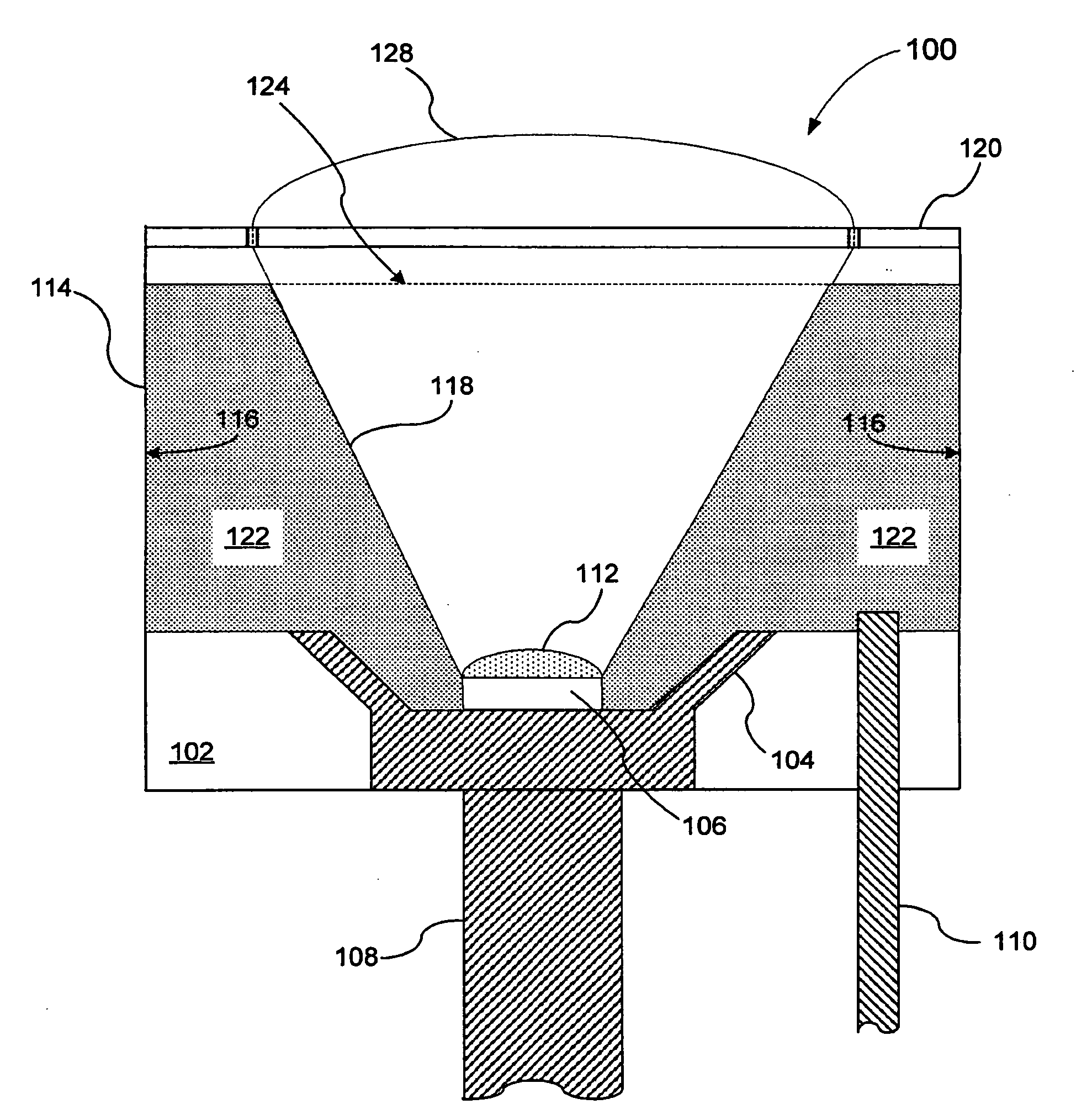
[0017]In FIG. 1, a cross-sectional side view illustrating an example of an implementation of a light emitting device that utilizes an hermetically sealed metal can package to house a light source is shown. The metal can package may be filled with an inert, heat conducting gas or liquid. The light emitting device having a hermetically sealed package (“LED-HSP”) 100 includes a substrate 102 having a concave base cavity 104 in which a light source 106, such as a light emitting diode (“LED”), may be placed. As an example, the substrate 102 may be a metal base that may function as a heat sink and may also inclu...


PUM


Abstract

A light emitting device having an hermetically sealed package that includes a light source positioned in a metal can container on which is placed an optically-transparent cover. An enclosed space formed by the metal can container and the optically-transparent cover may be filled with an inert, heat-conducting gas or liquid and the inner surface of the metal can container may be coated with a high-reflector material that prevents absorption of the light emitted by the light source. A method of producing a light-emitting device having an hermetically-sealed package and a method of dissipating heat from a light-emitting device having an hermetically-sealed package is also provided.

Description

BACKGROUND OF THE INVENTION[0001]Light emitting diodes (“LEDs”) are, in general, miniature semiconductor devices that employ a form of electroluminescence resulting from the electronic excitation of a semiconductor material to produce visible light. Initially, the use of these devices was limited mainly to display functions on electronic appliances and the colors emitted were red and green. As the technology has improved, LEDs have found a wide range of new uses and applications.[0002]In the manufacturing process, the LEDs may be mounted on a substrate that may include an integrated circuit (“IC” or “chip”) or a printed circuit board (“PCB”), and may also have terminals or leads attached. It is appreciated by those skilled in the art that each of the LEDs or substrate may be described as a “die,” which refers to an individual monolithic device and therefore may be interchangeably used with the terms “IC” and “chip.” The LEDs may be mounted using conductive paste because the substrat...

Claims


Application Information

Patent Timeline
IPC IPC(8): F21V29/00
CPCH01L33/56H01L33/647H01L33/641H01L2224/48091H01L2224/48247Y10S362/80H01L2224/48464H01L2924/00014
Inventor TAJUL, AROSH BAROKYCHUA, JANET BEEYIN
Owner AVAGO TECH INT SALES PTE LTD
Learn More