
Night-Vision System For Motor Vehicles Having A Partial Optical Filter

a technology of partial optical filter and night vision system, which is applied in the direction of optical radiation measurement, television system, instruments, etc., can solve the problems of increasing the cost of the correspondingly equipped night vision control device, uneven illumination of the region detected via the camera, and difficulty in detecting critical details in the far rang

Inactive Publication Date: 2007-12-06
ROBERT BOSCH GMBH
View PDF5 Cites 23 Cited by
  • Summary
  • Abstract
  • Description
  • Claims
  • Application Information

AI Technical Summary

Benefits of technology

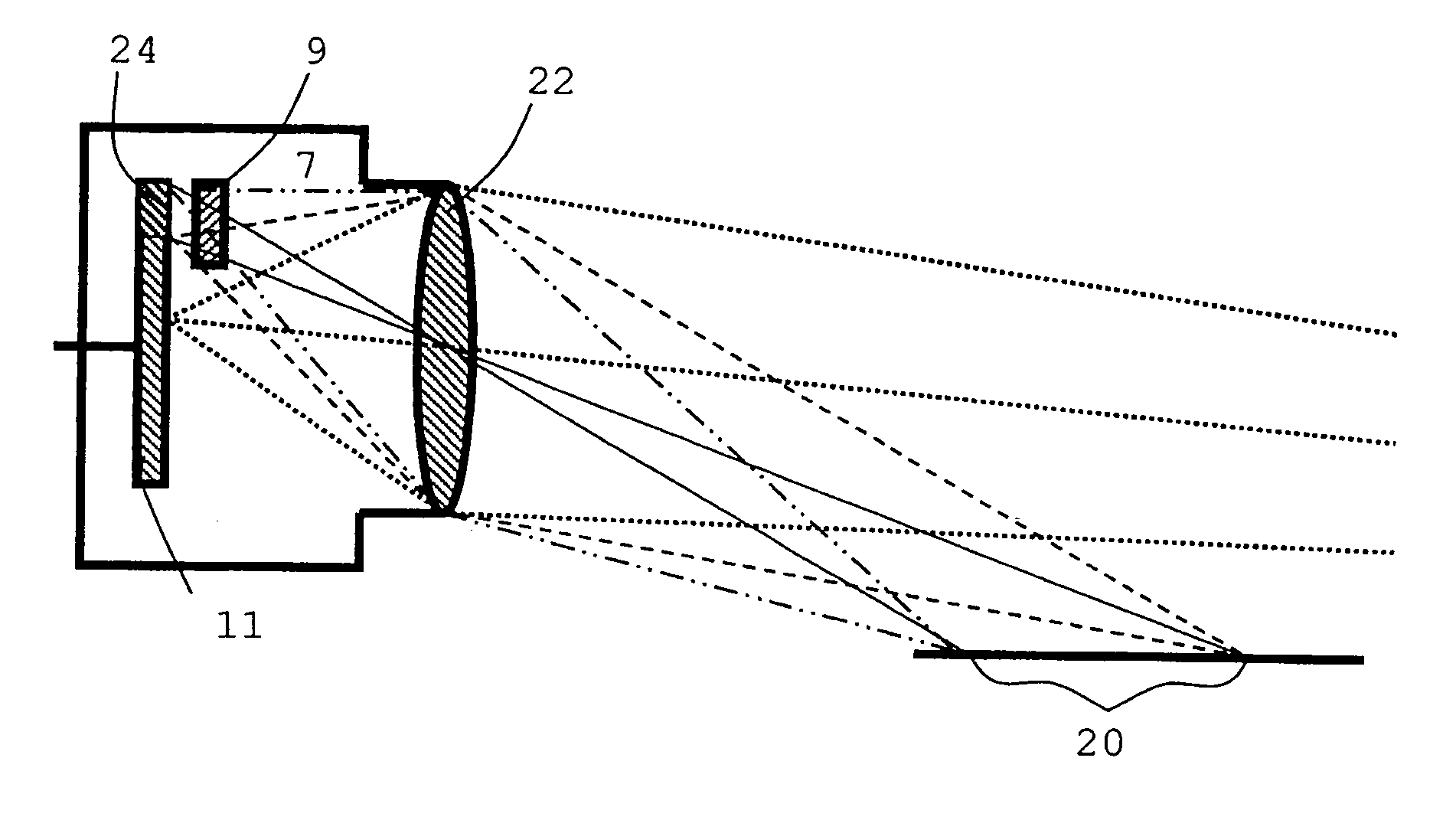
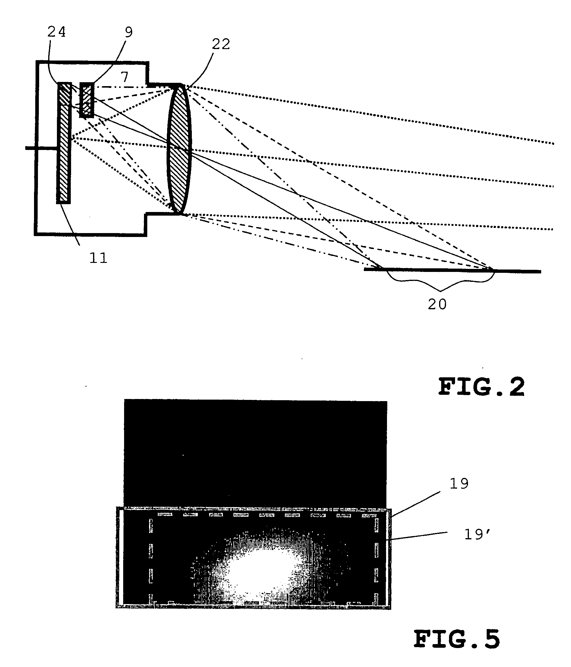
[0013] The present invention make it possible to attenuate the recorded radiation on predefined partial regions of the image-sensor surface of the camera of the night-vision system that would otherwise be regularly exposed to undesired high radiation intensity, such attenuation being implementable without the aid of image-processing software algorithms. Since according to the present invention the attenuation of the radiation in predefined partial regions is effected by an optical filter element appropriately disposed in the optical path of the night-vision system, the radiation is reduced in the desired image regions, for example the image of the excessively bright close range, in particular, even prior to being recorded. For the purpose of the present invention, the optical path denotes the path from the illuminated object to the imager. For the present invention, suitable positions of the filter element are positions in the section immediately in front of and / or within the camera.
[0014] This arrangement dispenses with costly software algorithms for image postworking in order to dim image areas that would normally have an undesired excessive brightness. In an uncomplicated manner, the driver's gaze is focused more on the image sections that are of interest for night vision assistance. Overmodulation of partial regions of the image-sensor surface is avoided, and the available brightness dynamics of the camera and display with respect to the image regions relevant for night-vision assistance are utilized in an optimal manner.
[0015] An advantageous example embodiment of the system according to the present invention includes a camera, which is sensitive in a wavelength range of 380 to 1100 nm. The radiation is recorded both from the VIS and NIR range, which improves the quality of the night-vision assistance (LED brake lights and tail-gate lights, for example, are visible as well).

Problems solved by technology

One particular problem in pure NIR systems and in the combined NIR-VIS systems is the uneven illumination of the region detected via the camera.
Furthermore, the driver's attention becomes increasingly drawn to the bright close range, thereby making it more difficult to perceive critical details in the far range.
Dimming of areas that are brighter than desired, computer-implemented by software algorithms in the processing of the image (in pure display systems also known as image processing), requires complicated computer work and additional memory capacity, which increases the cost of the correspondingly equipped night-vision control device.
In basic night-vision systems, which do not include an image-processing computer, such software-based postworking of the camera image is not possible.
Overmodulations of the imager due to limited brightness dynamics are also no longer able to be corrected by software-based postprocessing.
In addition, a wavelength-dependent attenuation of the close range via software algorithms is not possible in gray-value cameras, and only with great effort in the case of color cameras.

Method used


Image

  • Night-Vision System For Motor Vehicles Having A Partial Optical Filter
  • Night-Vision System For Motor Vehicles Having A Partial Optical Filter
  • Night-Vision System For Motor Vehicles Having A Partial Optical Filter

Examples


Embodiment Construction

[0028] In the figures, identical or functionally equivalent components are denoted by matching reference numerals.

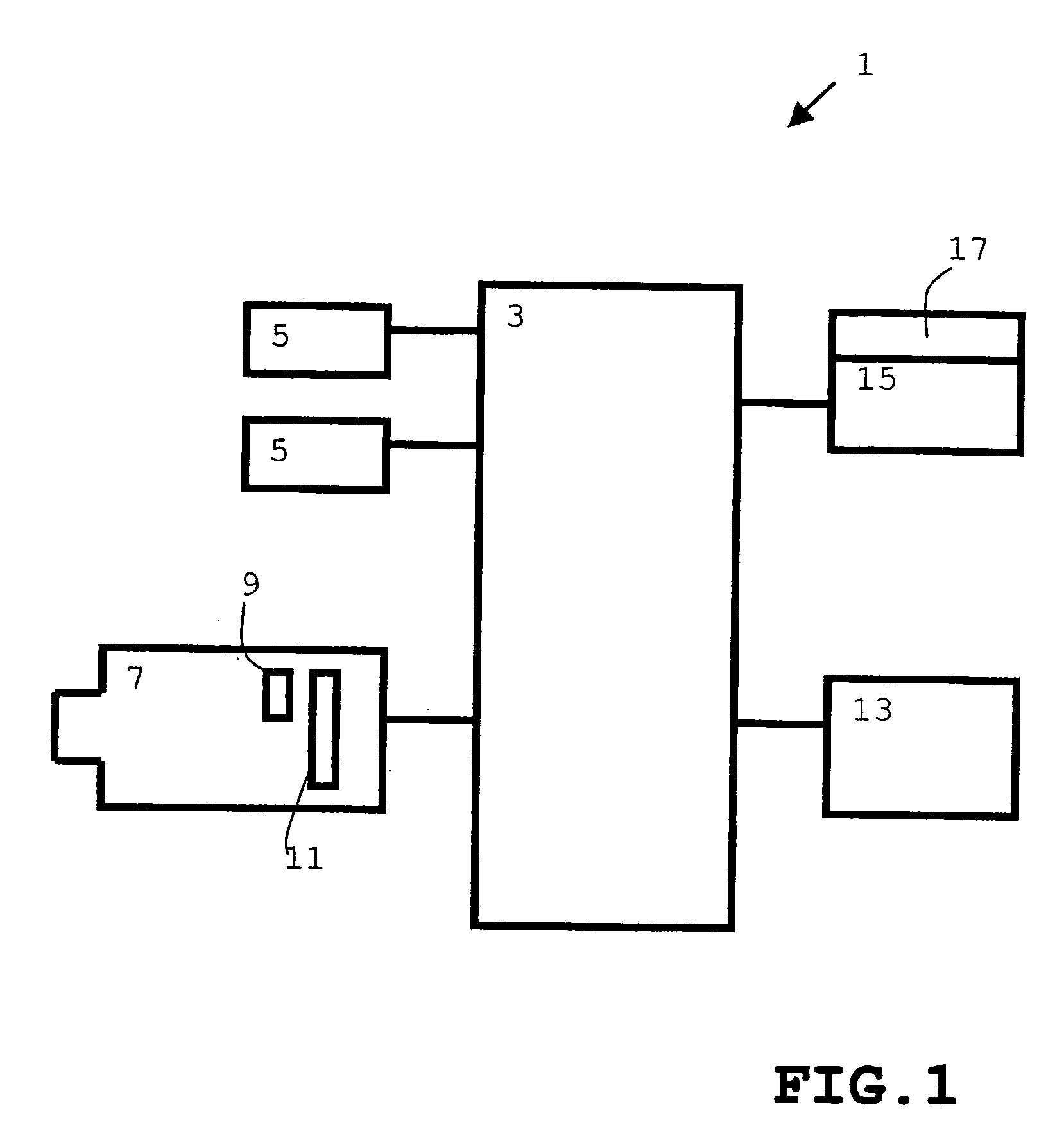
[0029]FIG. 1 shows a block diagram of an example embodiment of night-vision system 1 for motor vehicles according to the present invention. Night-vision system 1 includes a control unit 3, which is connected to the additional components of the system, controls the additional components and processes their signals and data.

[0030] Upon activation of the night-vision system by an operating unit 13, control unit 3 turns on NIR high-beam headlights 5. These headlights 5 illuminate a spatial range in the NIR wavelength range (780 to approximately 1100 nm) in front of the vehicle that is similar to that of conventional high beam headlights. The illumination range amounts to approximately 250 meters.

[0031] A camera 7, which is sensitive also to the NIR range and includes a CCD or CMOS image sensor (with linear or non-linear intensity characteristic in each case) and has a dep...


PUM


Abstract

A night-vision system for motor vehicles includes a camera having a radiation-sensitive image-sensor surface, which is configured for recording electromagnetic radiation from the infrared range, in particular. To improve distant-vision characteristics beyond the low-beam range, the system according to the present invention includes a filter element which is positioned in the optical path of the night-vision system in such a way that it causes an attenuation of the recorded radiation to predefined partial regions of the image sensor. This allows an attenuation of the radiation from the low-beam range, which would otherwise be too intense.

Description

FIELD OF THE INVENTION [0001] The present invention relates to a night-vision system for motor vehicles, which includes a camera having an image sensor surface that is sensitive to radiation and which is configured to detect electromagnetic radiation from the near-infrared range. BACKGROUND INFORMATION [0002] Systems for night-vision assistance are becoming more common in motor vehicles. Night-vision systems serve the purpose of improving the driver's vision at night, beyond the range of a dimmed headlight, through the use of cameras and displays or windshield projections. The oncoming traffic must not be blinded by glare as would be the case with a conventional high beam, which also includes light in the visible range. [0003] Night-vision assistance is achieved by utilization and detection of wavelength ranges that are not visible to the human eye. These are made accessible to the driver via cameras, using displays or windshield projections (for instance, by head-up displays). [000...

Claims


Application Information

Patent Timeline
IPC IPC(8): G01J5/00G02B5/22B60R1/00G01S7/481G01S17/89G01S17/931G02B5/20G02B13/14G02B23/12H04N5/33
CPCB60R1/00B60R2300/106B60R2300/205B60R2300/804B60R2300/8053H04N5/33G01S17/89G01S17/936G02B5/208G02B13/14G01S7/4813G01S17/931B60R1/30B60R1/24H04N23/20
Inventor HAUG, KARSTEN
Owner ROBERT BOSCH GMBH
Learn More