
Lighting assembly and socket

Active Publication Date: 2014-02-06
KONINKLIJKE PHILIPS ELECTRONICS NV
View PDF19 Cites 1 Cited by
  • Summary
  • Abstract
  • Description
  • Claims
  • Application Information

AI Technical Summary

Benefits of technology

The present invention provides an improved lighting assembly and a socket for releasably connecting the lighting assembly to the socket in a reliable way. The invention reduces the space required for electrical contacting means in the lighting assembly and in the socket, which allows for better heat dissipation from the light source. The lighting module can easily be replaced without replacing the entire lighting assembly. The connector locking means is designed to provide efficient cooling of the light source. The heat sink is configured to dissipate the heat generated by the light source and transferred to the heat sink via the heat spreader. The thermal interface material used in the present invention provides a good thermal contact and allows for more freedom in the choice of the material compared to what may be used in other lighting assemblies.

Problems solved by technology

Furthermore, LEDs have a long operational lifetime.
However, even though LEDs have a long operational life, individual devices may fail and require early replacement or LED lamps may be replaced for reasons such as upgrading or alternating between different LED lamps.

Method used


Image

  • Lighting assembly and socket
  • Lighting assembly and socket
  • Lighting assembly and socket

Examples


Embodiment Construction

[0031]The present invention will now be described more fully hereinafter with reference to the accompanying drawings, in which example embodiments of the invention are shown. This invention may, however, be embodied in many different forms and should not be construed as limited to the embodiments set forth herein; rather, these embodiments are provided for thoroughness and completeness, and fully convey the scope of the invention to the skilled person. Like reference characters refer to like elements throughout.

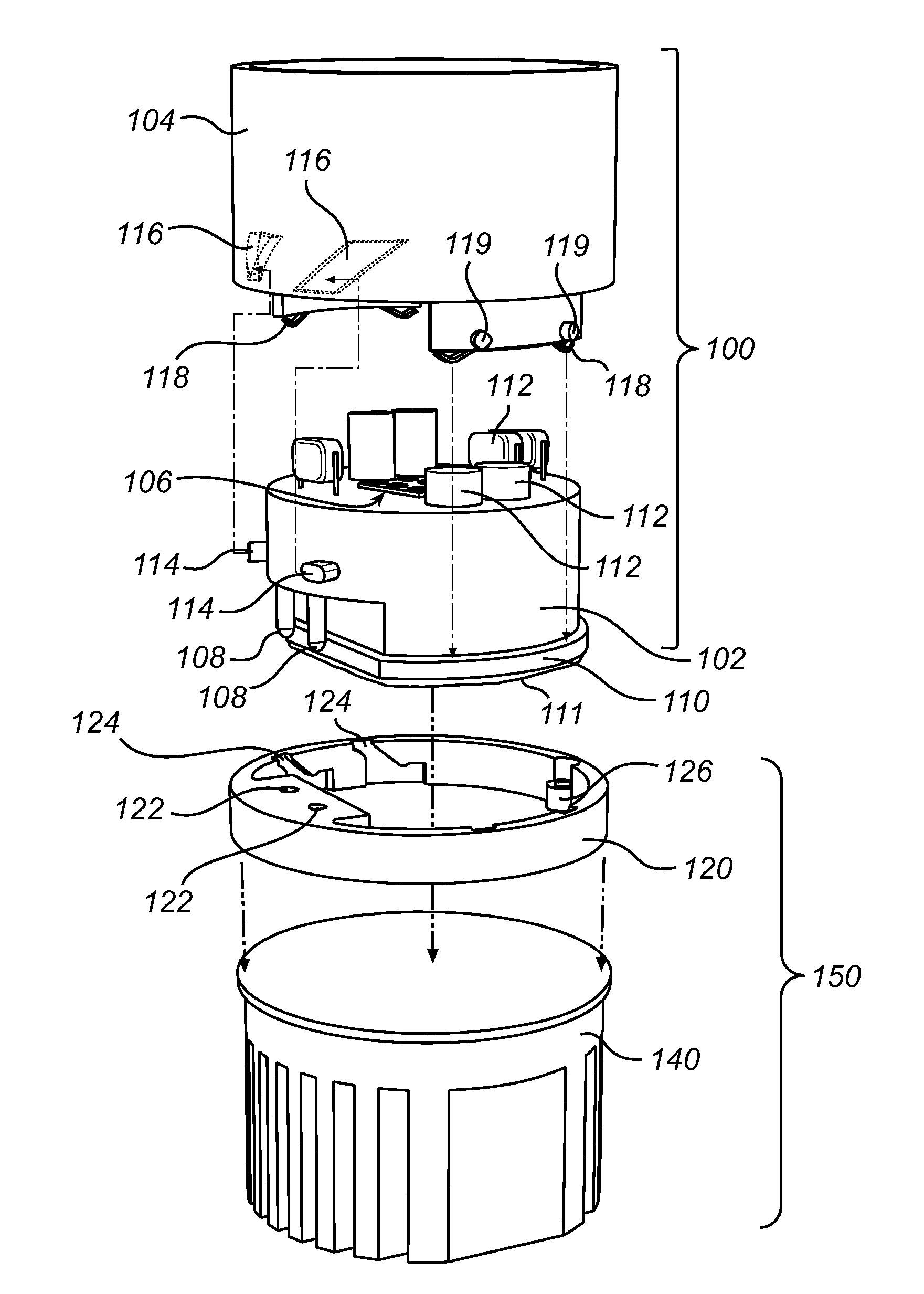
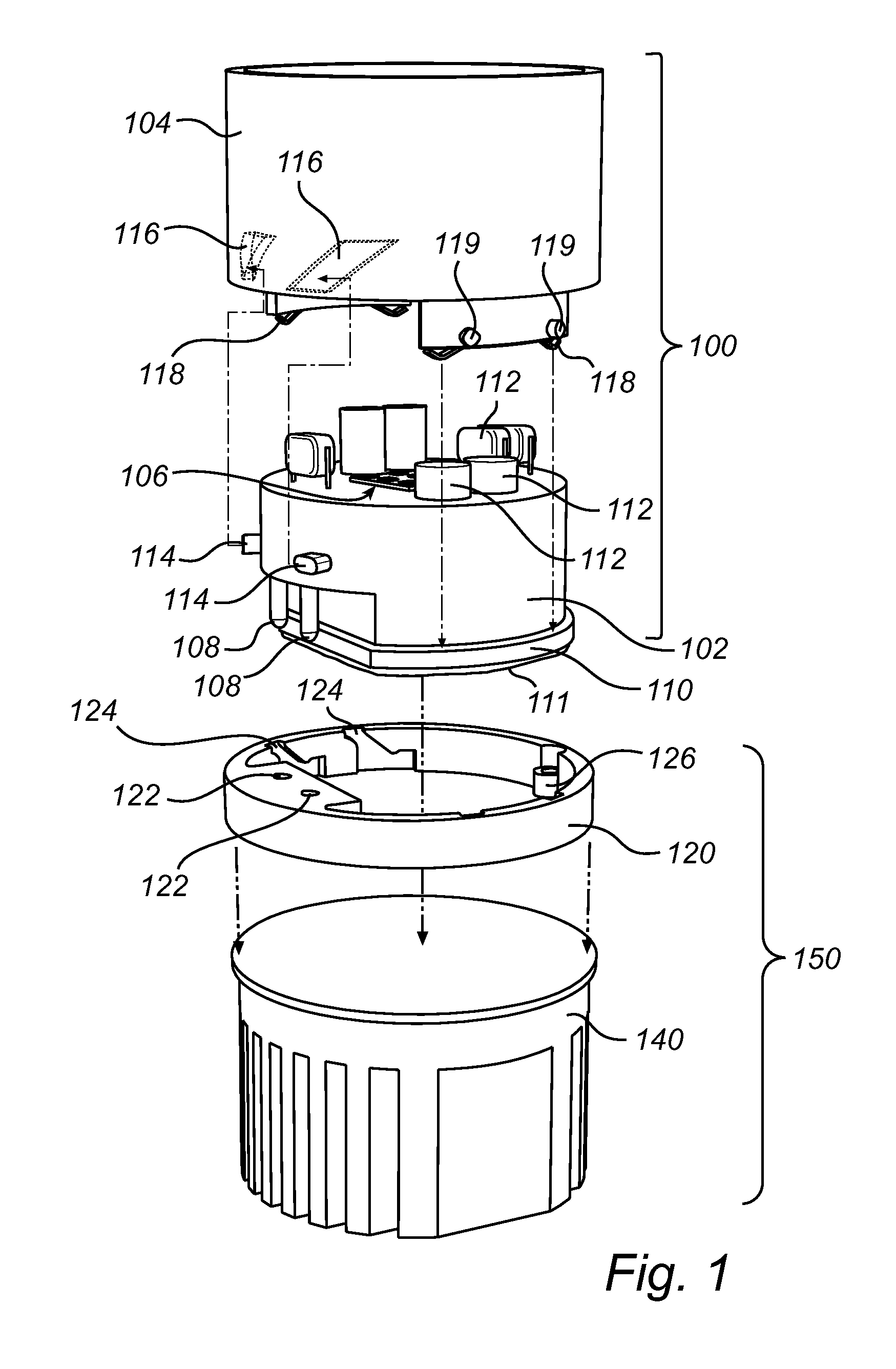
[0032]In the following detailed description, example embodiments of a lighting assembly according to the present invention are mainly discussed with reference to FIG. 1 illustrating a lighting assembly configured to be mechanically and electrically connected to a socket and a socket configured to receive the lighting assembly.

[0033]FIG. 1 schematically illustrates a lighting assembly 100 comprising a lighting module 102 and a connector 104 configured to be connected to the so...


PUM


Abstract

A lighting assembly (100) configured to be mechanically and electrically connected to a socket (150), the lighting assembly comprising a lighting module (102) comprising a light source (106), electrical contacting means (108) electrically connected to the light source and a heat spreader (110) in thermal contact with the light source; and a connector (104) being rotatable in relation to the lighting module (102). The connector comprises connector locking means (119) for locking the lighting assembly to a socket through interaction with receiving locking means comprised in the socket when the lighting module is axially inserted into the socket and the connector is rotated relative to the lighting module and the socket, thereby bringing the electrical contacting means (108) into contact with corresponding receiving contacting means (122) comprised in the socket. Hereby, the space required for electrical contacting means in the lighting assembly and in the socket may be reduced as no space is reserved in the socket for rotation of the electrical connecting means.

Description

FIELD OF THE INVENTION[0001]The invention relates to a lighting assembly and to a socket for receiving the lighting assembly.BACKGROUND OF THE INVENTION[0002]Light emitting diodes, LEDs, are employed in a wide range of lighting applications. As LEDs have the advantage of providing a bright light, being reasonably inexpensive and drawing very little power, it is becoming increasingly attractive to use LEDs as an alternative to traditional incandescent lighting. Furthermore, LEDs have a long operational lifetime. As an example, LED lamps may last 100 000 hours which is up to 20 times the operational life of an incandescent lamp.[0003]However, even though LEDs have a long operational life, individual devices may fail and require early replacement or LED lamps may be replaced for reasons such as upgrading or alternating between different LED lamps.[0004]Therefore, serviceable and integrated LED modules with corresponding sockets for general lighting applications are introduced to the ma...

Claims


Application Information

Patent Timeline
IPC IPC(8): F21V19/00
CPCF21V19/001F21V19/0005F21V23/06H01R33/9456F21V29/70F21V29/713F21V29/763F21K9/20F21Y2115/30F21Y2115/10F21V23/006
Inventor KESER, MERIJNDEURENBERG, PETER HUBERTUS FRANCISCUSCREUSEN, MARTINUS PETRUS
Owner KONINKLIJKE PHILIPS ELECTRONICS NV
Learn More