
Suction apparatus equipped with ejector

a suction apparatus and ejector technology, applied in the direction of thin material processing, application, article separation, etc., can solve the problems of troublesome maintenance thereon including exchange of components and the like, complex structure, unstable top portion of the assembly, etc., to achieve easy maintenance operations, simplified structure of the suction apparatus as a whole, and easy operation

Active Publication Date: 2013-09-03
SMC CORP
View PDF13 Cites 1 Cited by
  • Summary
  • Abstract
  • Description
  • Claims
  • Application Information

AI Technical Summary

Benefits of technology

The simplified structure facilitates easier maintenance and improved workpiece positioning accuracy, with reduced weight and enhanced transfer efficiency.

Problems solved by technology

Thus, the structure is complex and maintenance thereon including exchange of component parts and the like is troublesome.
As a result, the top portion of the assembly is in an unstable condition with an abundance of heavy objects thereon.
In addition, when workpieces are transported, the posture of workpieces transported by the suction cup also is unstable, such that the workpieces cannot be positioned reliably at a desired location.

Method used


Image

  • Suction apparatus equipped with ejector
  • Suction apparatus equipped with ejector
  • Suction apparatus equipped with ejector

Examples


Embodiment Construction

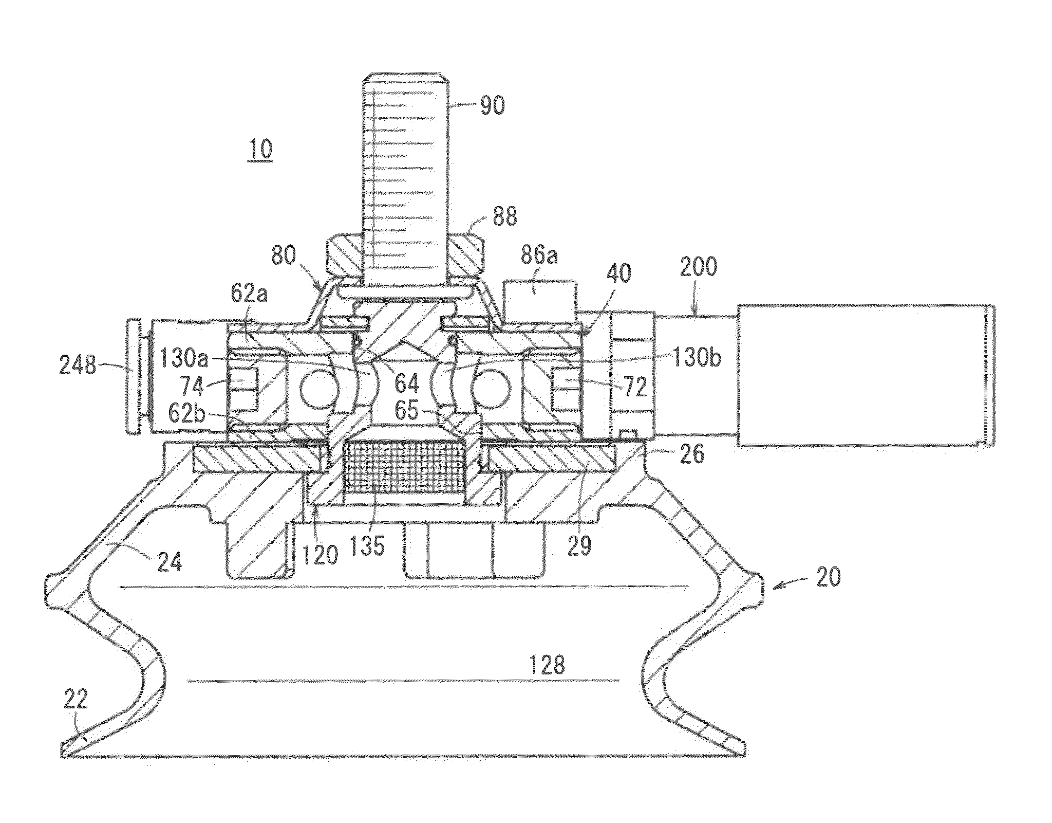
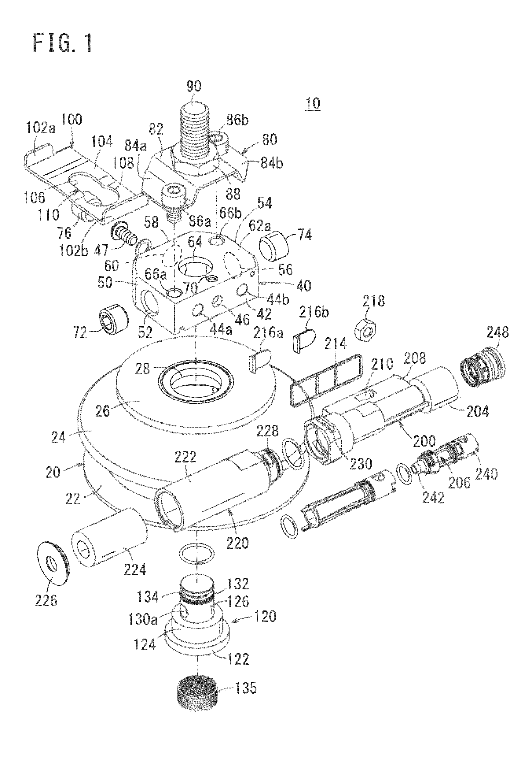
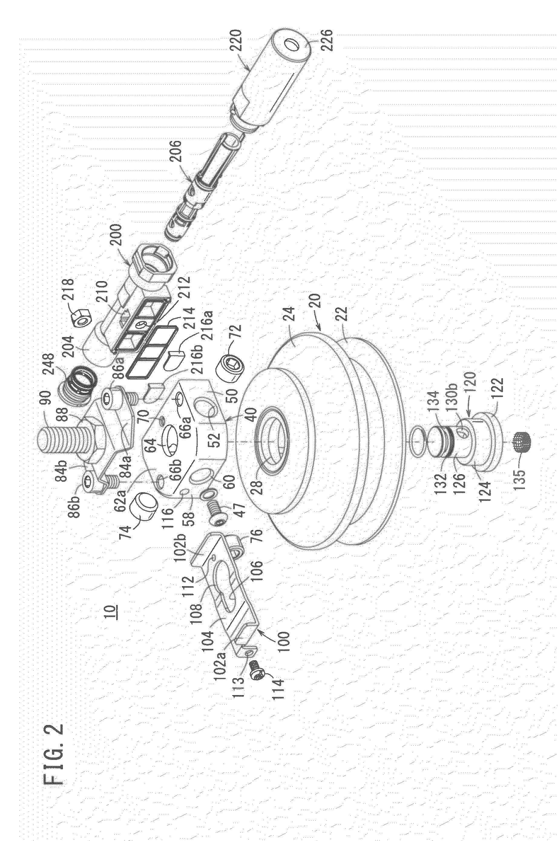
[0018]In FIG. 1, reference numeral 10 indicates an ejector equipped suction apparatus (hereinafter also referred to simply as a suction apparatus) according to an embodiment of the present invention. The suction apparatus 10 includes a suction pad 20, an adapter plate 40, a mounting bracket 80, a lock plate 100, a retaining stud 120, and an ejector 200.

[0019]The suction pad 20 comprises a skirt portion 22 equipped with a suction surface that contacts a workpiece and retains the workpiece under suction, a cushion portion 24 connected to the skirt portion 22, and a mounting portion 26 formed at a location where the cushion portion 24 terminates. A hole 28 through which a second cylindrical section 126 of a later-described retaining stud 120 is inserted is formed in the center of the mounting portion 26. The skirt portion 22, the cushion portion 24, and the mounting portion 26 are constituted together integrally, and are formed from a flexible material, for example, synthetic resin, sy...


PUM


Abstract

A retaining stud is inserted from a bottom portion of a suction pad that constitutes part of an ejector equipped suction apparatus, and an end of the retaining stud is inserted into an adapter plate. Further, a small diameter portion of a lock plate engages with a lock plate groove, which is exposed externally on the retaining stud, whereby the retaining stud and the lock plate are connected together integrally. In addition, an ejector is fixed using a side wall portion of the adapter plate. A mounting bracket is attached to the adapter plate while covering the lock plate, and a transfer means such as a robot arm or the like is fixed to the mounting bracket using a bolt.

Description

CROSS-REFERENCE TO RELATED APPLICATION[0001]This application is based upon and claims the benefit of priority from Japanese Patent Application No. 2011-084875 filed on Apr. 6, 2011, of which the contents are incorporated herein by reference.BACKGROUND OF THE INVENTION[0002]1. Field of the Invention[0003]The present invention relates to a suction apparatus equipped with an ejector, which is capable of attracting a workpiece under suction by a negative-pressure fluid, and of transporting the workpiece to a predetermined location.[0004]2. Description of the Related Art[0005]Recently, vacuum suction apparatus have widely been used for transporting and positioning thin-plate workpieces. Such a vacuum suction apparatus is equipped with a main body into which a compressed fluid is supplied, and a suction pad that is fixed to the main body. Compressed fluid, which is supplied to the main body, creates a negative pressure state in the interior of the suction pad that is in contact with a wor...

Claims


Application Information

Patent Timeline
Patent Type & Authority Patents(United States)
IPC IPC(8): B25J15/06
CPCB25B11/007B65G47/91B65H3/0883B65H2402/515B65H2601/324B65H2402/51B25J15/0616B25J15/0675B65G47/911
Inventor FUKANO, YOSHIHIROSUGANO, KOJIOBATA, YASUHIKOSASAKI, AKIRA
Owner SMC CORP
Learn More