Bioabsorbable, deformable fixation material and implant

Inactive Publication Date: 2007-11-22
BIORETEC
View PDF17 Cites 25 Cited by
  • Summary
  • Abstract
  • Description
  • Claims
  • Application Information

AI Technical Summary

Benefits of technology

[0026]An advantage of the present invention is to provide a low profile oriented biocompatible plate implant with orientation gradient structure and with sufficient strength to be operable for enhancing a substantially secured relation between a plurality of adjacent bone portions. Further advantages of the invention are to provide a biocompatible plate implant of the above-mentioned type, which[0027]is bioresorbable over a desired period of time while not generating a substantial inflammatory response,[0028]is relatively rigid at a first thermochemical state, but is also relatively deformable at said first thermochemical state prior to implantation,[0029]is repetitively deformable at the said first thermochemical state prior to implantation,[0030]can be easily and inexpensively manufactured with continuous, semi-continuous or non-continuous processes, and[0031]is operable to enhance a secured relation between the oriented biocompatible fixation device (plate) and one or more adjacent bone portions.
[0027]is bioresorbable over a desired period of time while not generating a substantial inflammatory response,
[0028]is relatively rigid at a first thermochemical state, but is also relatively deformable at said first thermochemical state prior to implantation,
[0029]is repetitively deformable at the said first thermochemical state prior to implantation,
[0030]can be easily and inexpensively manufactured with continuous, semi-continuous or non-continuous processes, and
[0031]is operable to enhance a secured relation between the oriented biocompatible fixation device (plate) and one or more adjacent bone portions.

Problems solved by technology

However, because of inadequate strength, some of the fracture fixation plates were broken in animal experiments.
Because the thermal conductivity of polymeric materials is poor, the conversion of material to a second temperature is a slow process.
Therefore, the clinical use of plates of U.S. Pat. No. 5,569,250 is tedious, slow and complex especially if the surgeon must shape the plate several times to make it fit exactly to the form of the bone to be fixed.
Although the said multilayer plate fits even the curved bone surface without heating of individual plates, the clinical use of multilayer plate is tedious, because the single plates easily slip in relation to each other before fixation.
Additionally the thickness of multilayer plate system easily becomes too thick for cranio maxillofacial applications, causing cosmetic disturbance and increased risks for foreign body reaction.
Random axial directions of oriented units could make the material structure unfavorable to resist shear (plate cutting) loads, which originate from the tendency of bone fragments to move (glide) in relation to each others in the direction of fracture plane (typically in the plane perpendicular to the flat surface and long axis of the plate).
Uniaxially oriented plate material has good mechanical strength in the tensile mode but it is strongly anisotropic so that longitudinal splitting of the material is a risk, when mechanical forces are stressing the plate.
On the other hand, biaxial orientation reduces the good tensile strength and shear strength of uniaxially oriented material.

Method used


Image

  • Bioabsorbable, deformable fixation material and implant
  • Bioabsorbable, deformable fixation material and implant
  • Bioabsorbable, deformable fixation material and implant

Examples


example 1

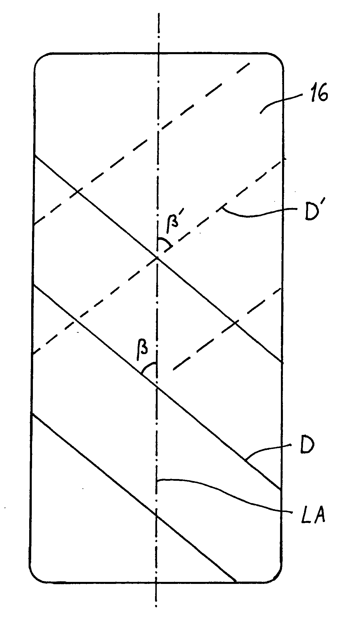
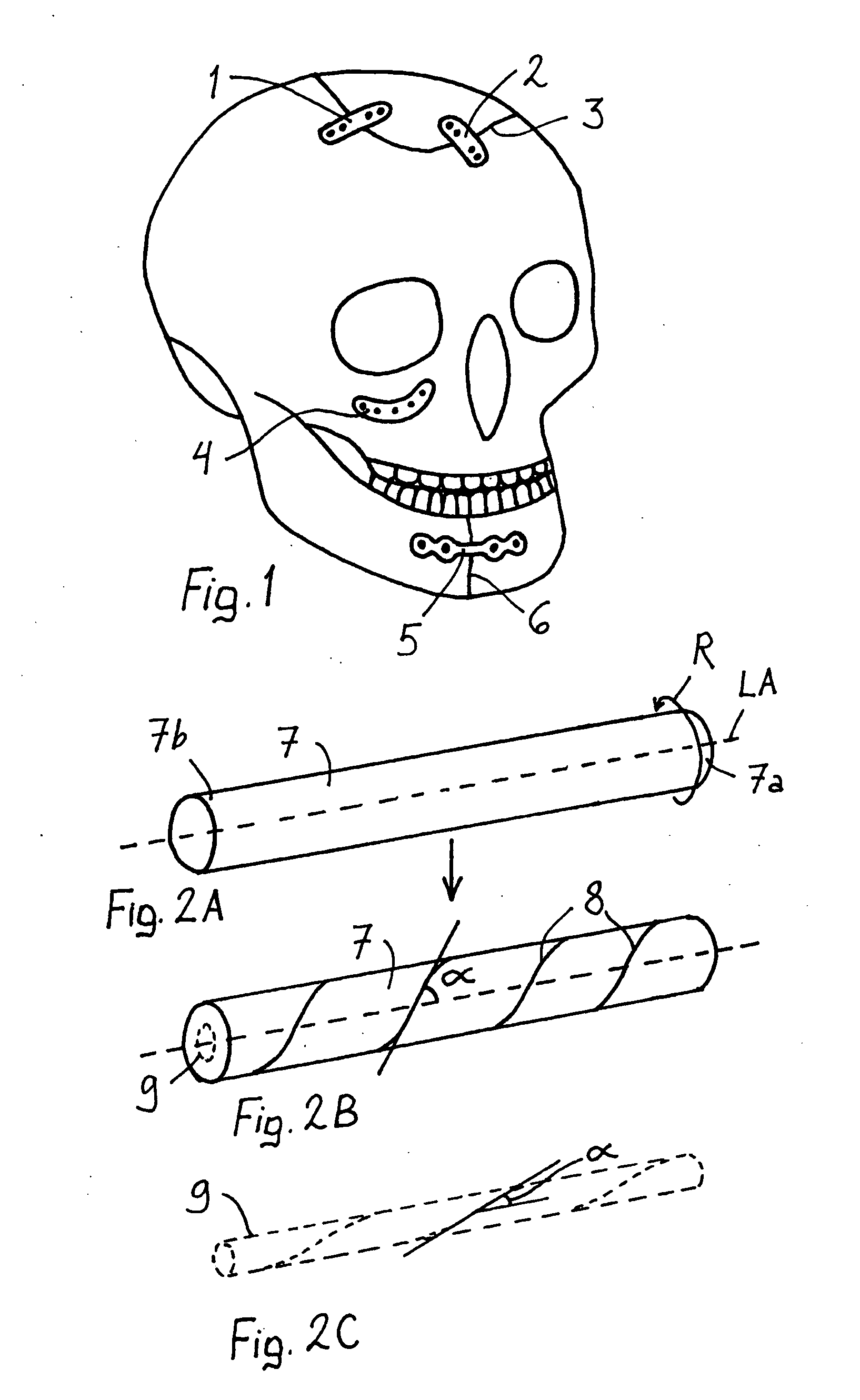
[0135]Commercially available medical grade PLGA 85L / 15G polymer granulate [Boehringer Ingelheim, Germany; polymer having inherent viscosity 5.5 dl / g, when measured at 25° C. as dissolved in chloroform (20 mg / 20 ml)] was melt extruded with a custom made 20 mm twin screw extruder to an elongated cylindrical rod (diameter=6.1 mm) which was cooled to room temperature. The inherent viscosity of such a melt extruded preform was about 3.5 dl / g. The melt extruded preform was fastened at one end to a moving part of a custom made plate manufacturing device. Another (not moving) fastening point was 60 mm apart from the fastened end of the preform. The preform between the fastening points was heated with hot air to about 80° C. The moving part was pulled 88 mm along the longitudinal axis of the preform, thus the preform was longitudinally stretched from 60 mm to 148 mm yielding a draw ratio of 2.5. The moving part was then rotated 4 rounds around the longitudinal axis of the preform, which was ...

example 2

Hole Tear Test

Equipment:

INSTRON 4411 (tensile testing machine at TTY / Institute of Biomaterials)

[0138]Crosshead speed: 10 mm / min

Cell: 5 kN

Gauge length 50 mm

[0139]Hole diameter in plate: 0.7 mm

Metal string was used as a material to tear the hole

[0140]Plates made from the same raw material by the same methods as in Example 1 were tested for the strength of the hole that is near the end of the plate. The hole was torn in the direction of long axis to the end edge with a metal string inserted through the hole. Maximum load / plate thickness was used as a test parameter. The results are summarized in FIG. 12. It can be seen that both helical orientation and helical orientation combined with uniaxial orientation increase the hole tearing strength compared with non-oriented and uniaxially oriented samples. Increase in the number of rounds per unit length in the helical orientation will also increase the tearing strength.

Surgical Methods of Using the Plate

[0141]As a summary, a method for secur...


PUM

PropertyMeasurementUnit
Timeaaaaaaaaaa
Temperatureaaaaaaaaaa
Shapeaaaaaaaaaa

Abstract

The invention relates to a bioabsorbable surgical osteosynthesis plate, operable to be secured by at least one fastener through at least one fastener opening formed in the plate to a bone. The osteosynthesis plate has first and second surfaces, and it is formed to one piece from a bioabsorbable polymer material that is oriented multiaxially and is substantially rigid and substantially deformable at a first thermochemical state. The plate comprises an oblique (diagonal) orientation gradient in relation to the direction of a reference axis of the plate.

Description

FIELD OF THE INVENTION[0001]The present invention relates to surgical materials and implants, method to manufacture such materials and implants and a method to use such materials and implants and, more particularly, bodily tissue fixation systems including bodily tissue fixation implants comprising bioabsorbable polymeric and / or composite plates.BACKGROUND OF THE INVENTION[0002]Because of shortcomings of metallic plates, bioabsorbable, polymeric plates have been developed for fracture fixation in bone surgery. E.g. elongated, bioabsorbable, six-hole plates were developed by Eitenmuller et al. for orthopaedic animal studies (European Congress on Biomaterials, Abstracts, Instituto Rizzoli, Bologna, 1986, p. 94). However, because of inadequate strength, some of the fracture fixation plates were broken in animal experiments.[0003]U.S. Pat. No. 5,569,250 describes a biocompatible osteosynthesis plate operable for being enhanced in a substantially secured relation to a plurality of adjace...

Claims


Application Information

Patent Timeline
IPC IPC(8): A61F2/30
CPCA61B17/80A61B17/8071A61B2017/00526A61B2017/00004A61B17/8085Y10T442/681A61L27/14A61L27/44A61L27/58A61L31/148
Inventor TORMALA, PERTTIHEINO, HARRIHUTTUNEN, MIKKO
Owner BIORETEC
Why Eureka
Try Eureka