
Radiant Burner

a burner and radiant technology, applied in the direction of incandescent mantels, combustion types, lighting and heating apparatus, etc., can solve the problems of burner surface and distributors, and achieve the effect of low nox emissions

Inactive Publication Date: 2007-11-22
ADVANCED PROPULSION TECH
View PDF25 Cites 15 Cited by
  • Summary
  • Abstract
  • Description
  • Claims
  • Application Information

AI Technical Summary

Benefits of technology

[0005] The present invention utilizes a heavy fuel and gas burner element having a substantially spherical shape to provide a radiant heat source with improved efficiency. The outer burner element is constructed of woven high temperature rated metal wires of sufficient diameter to withstand the heat of combustion occurring at its surface and small enough to result in mesh having a predetermined porosity that allows the micro-mist or gaseous fuel / air mixture to escape there-through.
[0009] The radiant burner of the present invention is shown in various environments including patio heaters which provide for unique configurations as compared with conventional heaters with central posts. This invention also can be used to generate heat energy for applications such as space heaters, wall furnaces, room heaters, garage heaters, fireplace heaters, “visual flame” type heaters and floor devices for homes, offices and recreational vehicles where high efficiency and low NOx emissions are desired.
[0014] It is a further object of the present invention to provide a radiant burner which is usable in a patio heater and other heat radiating devices in which low NOx emissions are desired.

Problems solved by technology

However in the patent, the burner surface and distributors are each limited to a hemispherical shape for use in boilers,

Method used


Image

  • Radiant Burner
  • Radiant Burner
  • Radiant Burner

Examples


Embodiment Construction

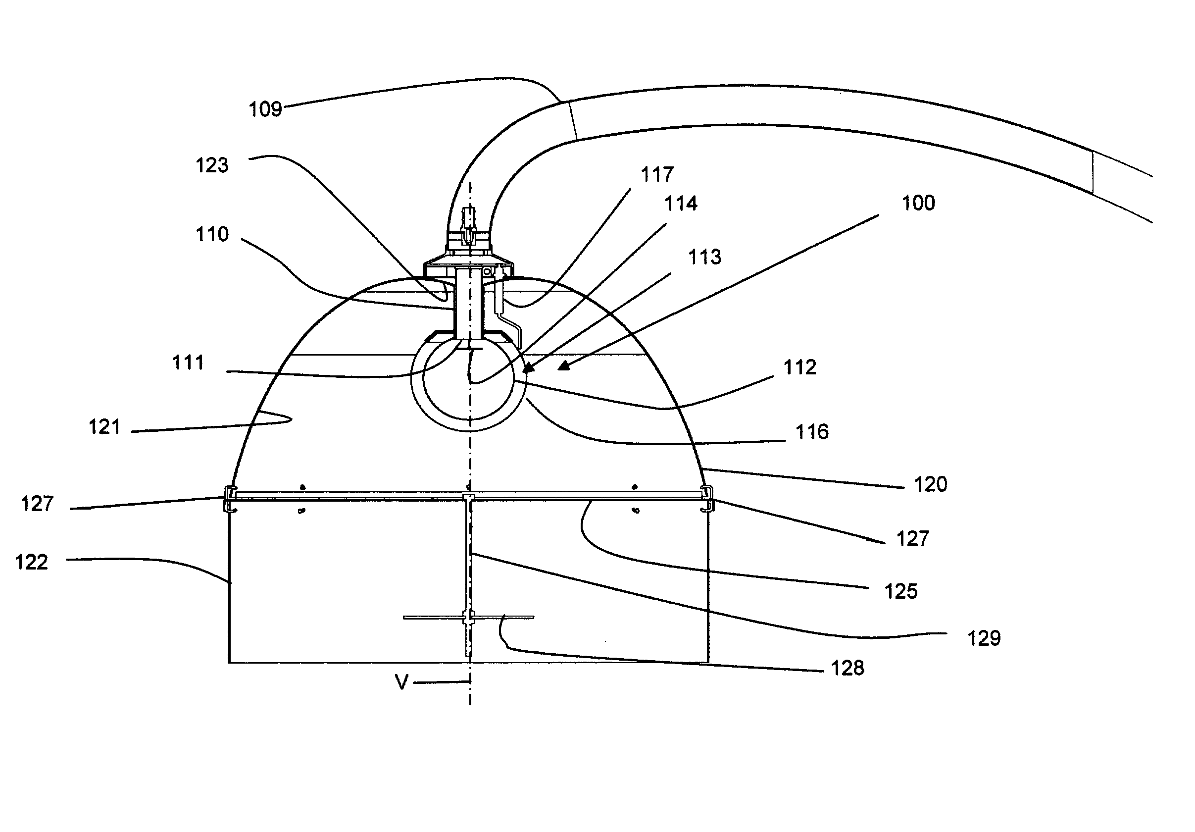
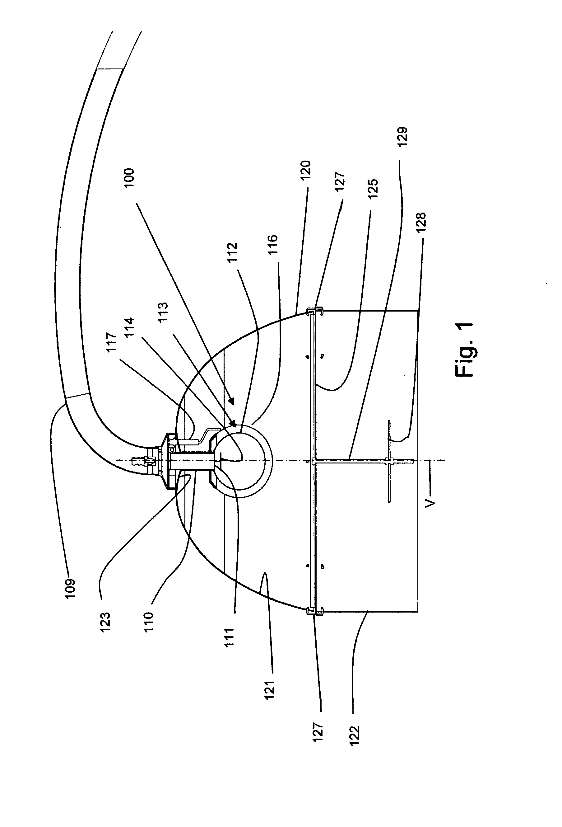
[0033] In FIG. 1, the preferred embodiment of the radiant burner assembly 100 of the present invention is shown in cross-section and configured in a patio heater. The parts of the assembly include a gas feed tube 110, a diffuser element 112, a distribution disk 114, a burner element 116 and a reflector element 120. As can be seen from FIG. 1, the diffuser element 112 and the burner element 116 are substantially spherical in shape and differently sized so as to define a substantially spherical space 113 between them. The distance between the diffuser element 112 and the burner element 116 is substantially less than the diameter of the diffuser element 112.

[0034] The gas feed tube 110 is connected to an extension arm 109 that serves to provide mechanical support and deliver the fuel and air mixture or a micro-mist from a pressurized source to the burner assembly. The gas feed tube 110 in turn provides a support structure for other elements of the burner assembly and a delivery path f...


PUM


Abstract

A highly efficient radiant burner assembly (100) for use in a patio heater or the like in areas where people prefer or require low NOX emissions. The efficiencies are created through the use of a spherical burner element (116) that is either formed of a high temperature steel wire mesh or stamping containing apertures of a predetermined size to allow combustion to remain within the burner element and to not cause the temperature of the burner element to exceed the temperature at which NOX are developed. Coating the burner with a catalyst also aids the low emission combustion process. Additional efficiencies are provided by atomizing the fuel before it is mixed with air and by the use of a laminar flow heat exchanger (940) that utilizes a fluid media flowing in a helical coil condenser unit.

Description

BACKGROUND [0001] 1. Field of the Invention [0002] The invention relates to the field of radiant burner systems for providing radiant heat energy through efficient combustion of a gaseous fuel / air mixture. More specifically the invention relates to the area of burner assembly and heat exchanger configurations for use in patio heaters, room heaters and space heaters, as well as other products that require efficient sources of radiant heat energy. Additional efficiencies are provided by utilizing heat exchangers to extract otherwise wasted heat from exhaust gas. [0003] 2. Description of the Prior Art [0004] Radiant heaters are known which use various configurations of wire mesh or perforated sheet metal burner elements to support combustion of a gaseous fuel / air mixture. The use of perforated sheet metal of the same configurations is also known to provide an even distribution of gases from the gas inlet port to the inner surface of the burner element. Some of these concepts are descri...

Claims


Application Information

Patent Timeline
Patent Type & Authority Applications(United States)
IPC IPC(8): F23D14/12
CPCF23D11/443F23D14/14F23D2900/14125F23D2203/1015F23D2203/1023F23D14/18F23D14/149F23D14/151F23D14/126F23D14/145
Inventor HOFBAUER, PETERHUANG, YUE XIN
Owner ADVANCED PROPULSION TECH
Learn More