
Medical marker means

Inactive Publication Date: 2007-11-15
BRAINLAB
View PDF14 Cites 10 Cited by
  • Summary
  • Abstract
  • Description
  • Claims
  • Application Information

AI Technical Summary

Benefits of technology

[0006] The present invention provides a medical marker that includes a marker body which can be positionally detected by a medical localization or tracking system. The marker body includes a luminescence agent which can be illuminated without an electrical energy supply coupled to the agent and / or body. In other words, self-illuminating and / or cold-illuminating agents are utilized that enable the marker to illuminate from the material itself, without an energy supply provided by cable or batteries. Thus, costly manufacture of reflective coatings for the markers is not required. Further, the markers have good luminisity (e.g., good recognizability for the respective marker means), and sterilization of the markers is relatively easy compared to prior art active markers. Another advantage is that the infrared (IR) irradiation, which typically is included in a camera system for detecting passive markers, can be omitted. IR radiation generally requires significant power, generates heat, and occasionally can disrupt other operating apparatus, such as video recorder remote controls, operating table remote controls or finger pulsometers.
[0009] Chemoluminescence, as mentioned above, is a luminescence (e.g., the emission of light in the visible range or also the emission of ultraviolet or infrared light) associated with a chemical reaction. In chemoluminescence, the temperature is significantly below the incandescent temperature of the substances involved and, therefore, is called “cold light”. This latter property makes chemoluminescence very suitable for medical applications, as it does not generate any disruptive, excess heat that has to be dissipated.
[0011] One example of chemoluminescence is the so-called “luminol reaction”, an example of an oxidation process in which the reaction energy is emitted not as heat but solely as light energy. The reaction is based on the oxidative release of nitrogen from phthalic acid hydrazide (luminol) by the action of alkali hydrogen peroxide. This reaction is catalysed by red prussiate of potash (hexacyanoferrate (III)). The luminescence can be triggered not only by hydrogen peroxide but also by ozone. In an alkali hydrogen peroxide solution, luminol shows a weak but sustained chemoluminescence, the intensity of which is strengthened by certain catalysts (potassium hexacyanoferrate (III), haemin), simultaneously reducing the decay time.
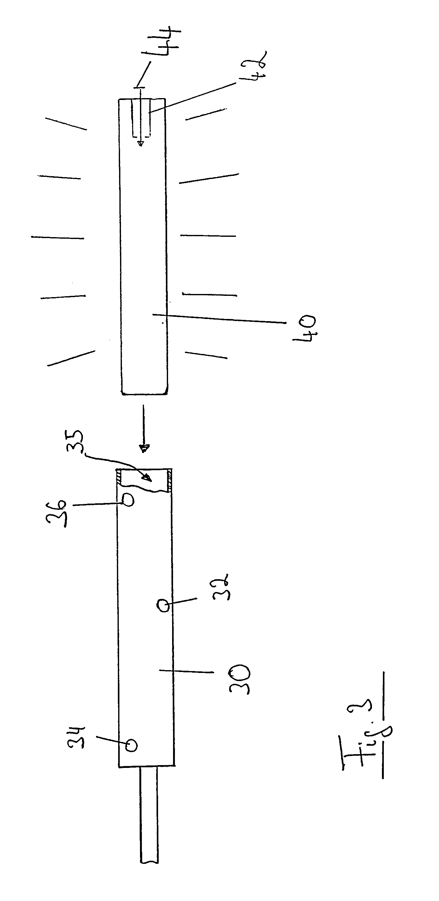
[0016] The marker body can form an insert which can be inserted into a receptacle of an instrument or treatment means, wherein translucent openings for the light emitted by the marker body are provided in or on the receptacle. Rod-shaped luminescent illuminating agents already available, for example, can be used for rod-shaped instruments. The translucent openings, which are inexpensive and simple to manufacture, can serve as the marker itself.

Problems solved by technology

Thus, costly manufacture of reflective coatings for the markers is not required.
IR radiation generally requires significant power, generates heat, and occasionally can disrupt other operating apparatus, such as video recorder remote controls, operating table remote controls or finger pulsometers.

Method used


Image

  • Medical marker means
  • Medical marker means
  • Medical marker means

Examples


Embodiment Construction

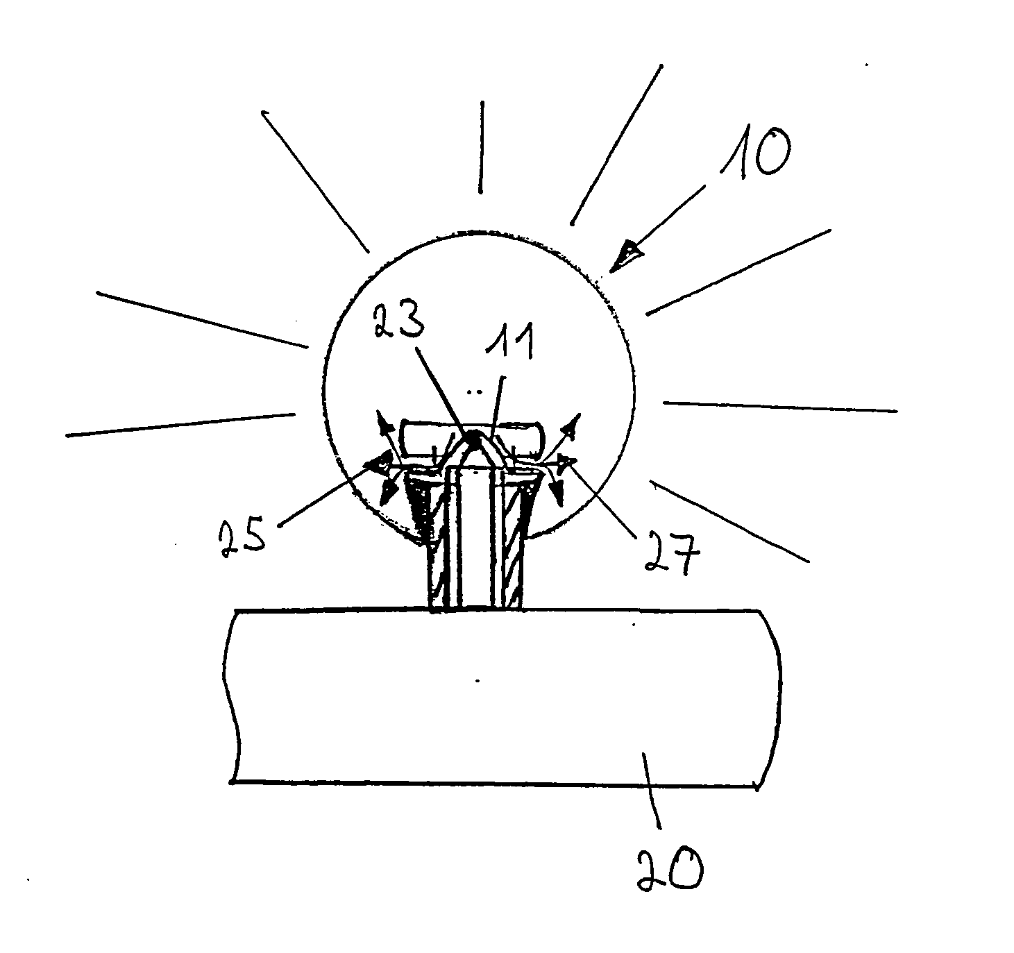
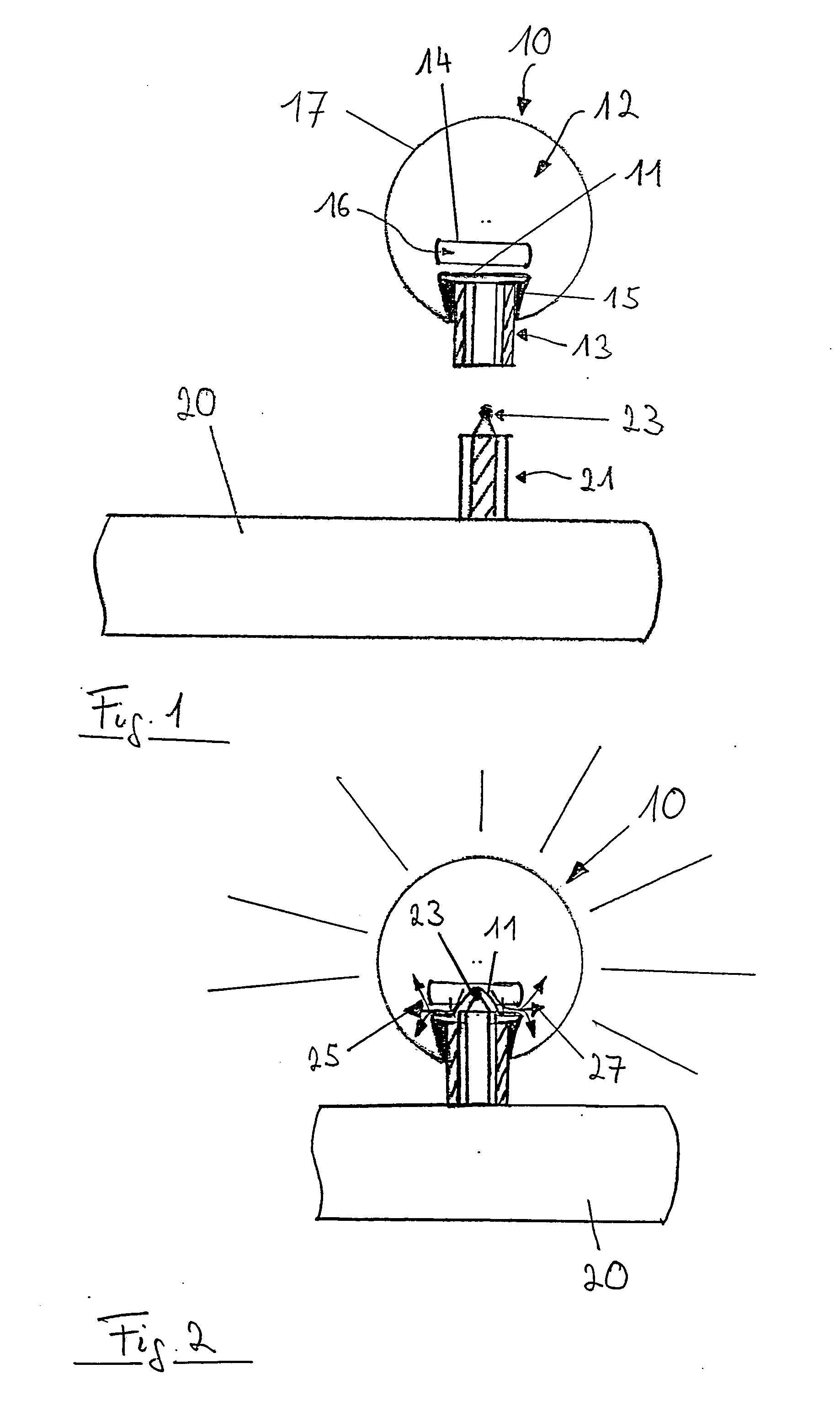
[0022]FIGS. 1 and 2 illustrate an exemplary marker fastening system for attaching an exemplary marker 10 to a surgical instrument 20. The marker 10 can be formed in a spherical shape and includes a casing which is permeable to light and / or diffusely permeable to light. A spherical part 17 of the casing connects to a connecting piece 15, which in turn connects to a membrane 11. The parts 11, and 17 together form an enclosed space. The connecting piece 15 connects the casing to a first fastening part of a socket 13, said first fastening part including an inner thread which extends in a central inner through-bore. Furthermore, a capsule 14 made of a breakable material is also fixed over the membrane 11.

[0023] While a first liquid 12 is situated in the spherical casing 17, the capsule 14 carries a second liquid 16. The two liquids are substances which, when mixed together, generate a chemoluminescence and preferably emit mainly in the infrared range (around 860 to 890 nm). In addition,...


PUM


Abstract

A medical marker trackable by a medical navigation system includes a marker body and a luminescence agent within the marker body. The luminescence agent is operative to emit light without an electrical power supply coupled to the luminescence agent.

Description

RELATED APPLICATION DATA [0001] This application claims priority of U.S. Provisional Application No. 60 / 738,546 filed on Nov. 21, 2005, which is incorporated herein by reference in its entirety.FIELD OF THE INVENTION [0002] The invention relates to medical markers and, more particularly, to a medical marker that utilizes a luminescence agent to emit a trackable signal. BACKGROUND OF THE INVENTION [0003] Active markers (e.g., LED markers) emit a trackable signal without the need for an external light source. Typically, such markers obtain power, for example, from an external power source via a cable connection or via an internal battery pack. Thus, instruments which are fitted with such active markers either have a cable attached thereto or are supplied with energy by batteries or power packs. [0004] Cables can be problematic, as they tend to obstruct the work area and / or make it difficult to handle the markers and / or instrument. Batteries or power packs, on the other hand, can be he...

Claims


Application Information

Patent Timeline
IPC IPC(8): F21K2/00
CPCA61B19/54A61B2019/5441A61B2019/444A61B90/92A61B90/39A61B2090/3941
Inventor BIRKENBACH, RAINER
Owner BRAINLAB
Learn More