
Materials and configurations for scalable microbial fuel cells

a technology configurations, applied in cell components, electrochemical generators, energy based wastewater treatment, etc., can solve the problems of limiting power production in the electrode configuration of microbial fuel cells, and achieve the effect of enhancing potential

Active Publication Date: 2007-11-08
PENN STATE RES FOUND
View PDF28 Cites 364 Cited by
  • Summary
  • Abstract
  • Description
  • Claims
  • Application Information

AI Technical Summary

Benefits of technology

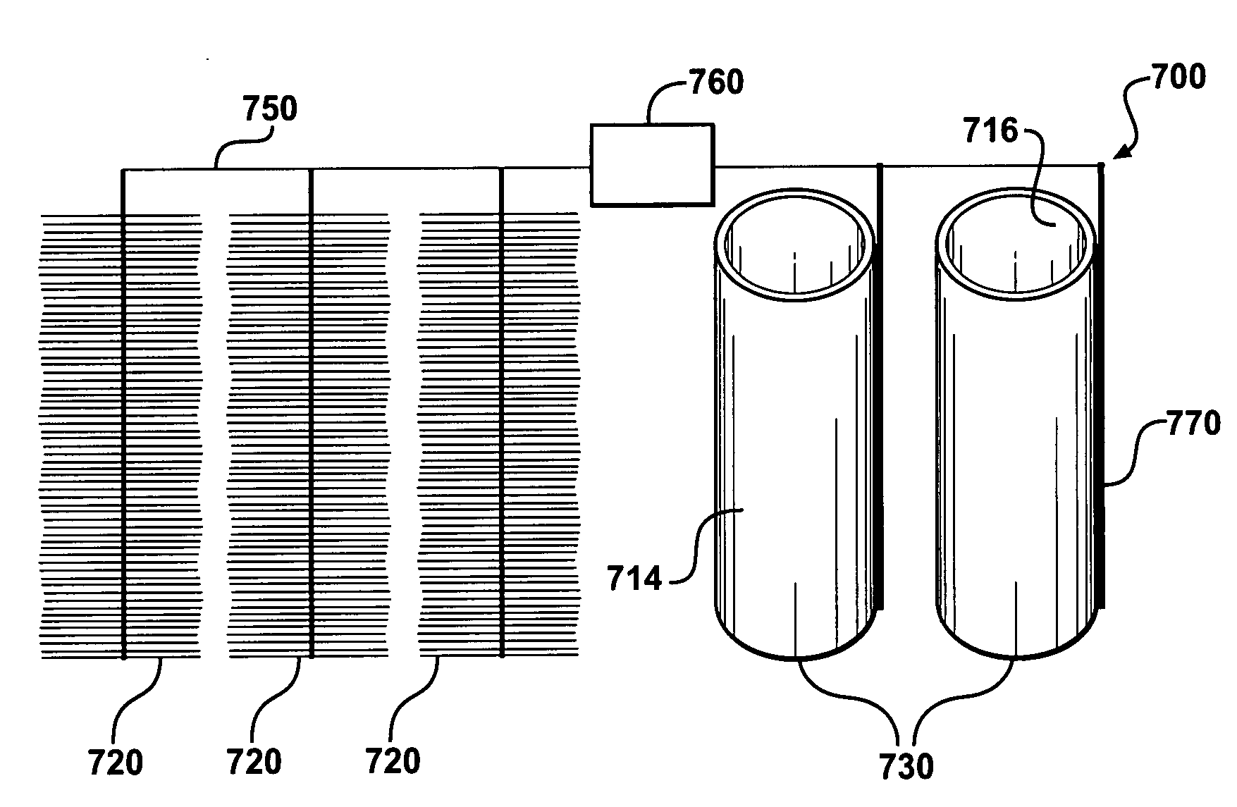
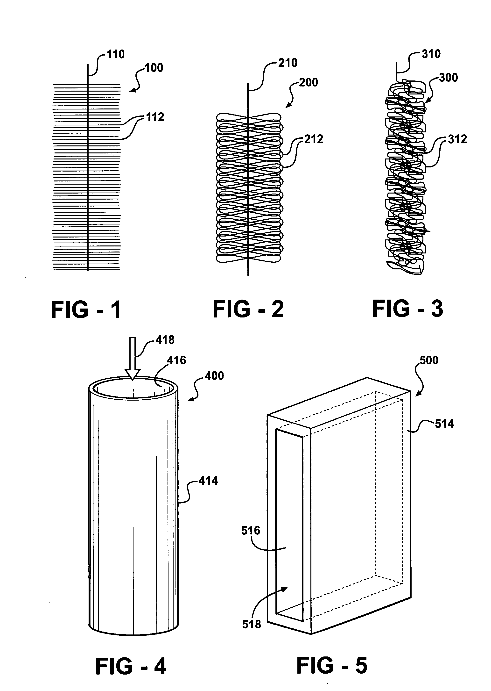
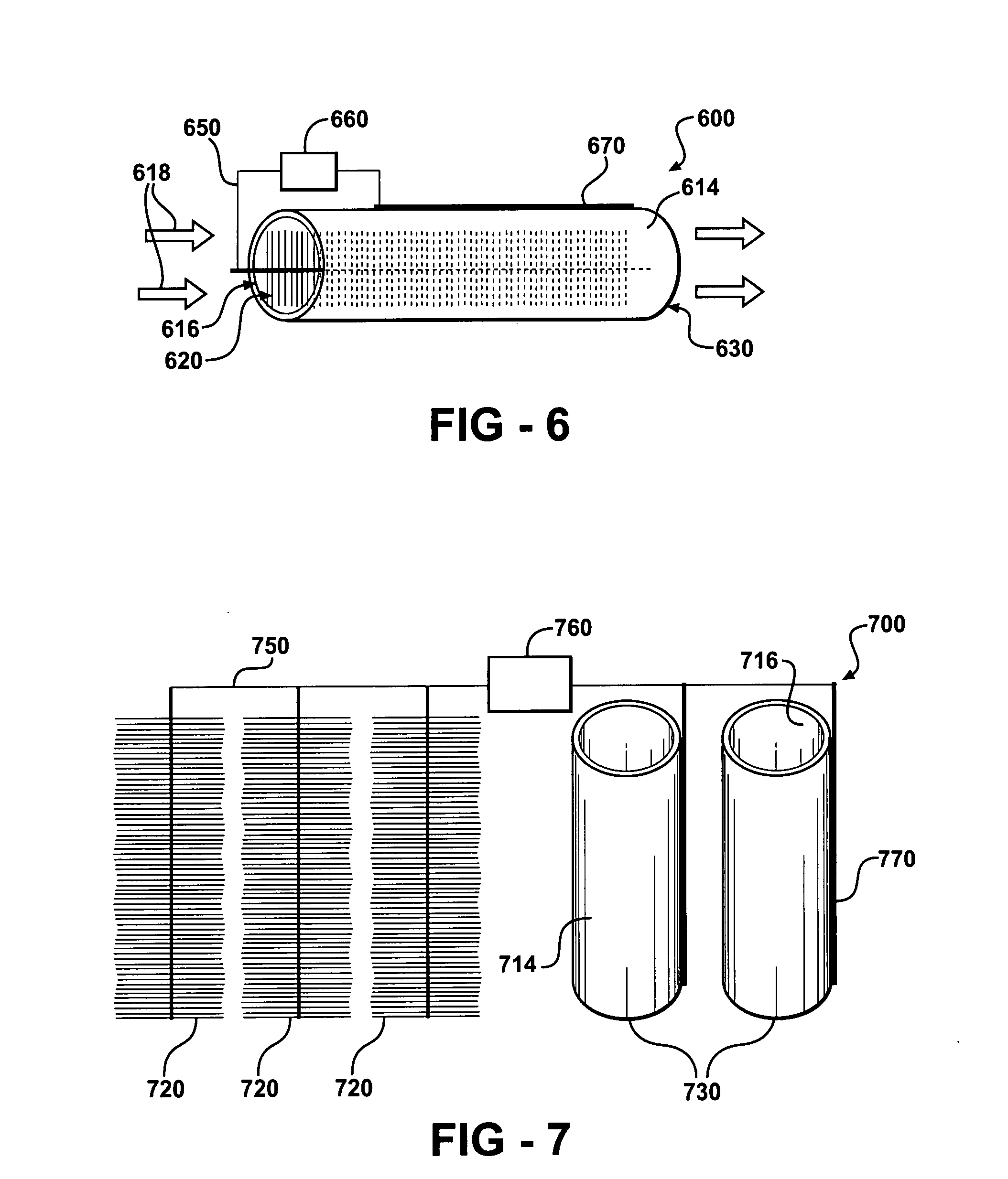
[0031]A method for production of electricity is described according to the present invention which includes providing a microbial fuel cell including a tube cathode and/or brush anode, inoculating the mic

Problems solved by technology

However, electrode configurations for microbial fuel cells often limit power production and figure prominently in space constraints associated with fuel cells.

Method used


Image

  • Materials and configurations for scalable microbial fuel cells
  • Materials and configurations for scalable microbial fuel cells
  • Materials and configurations for scalable microbial fuel cells

Examples


example 1

[0170]Electrode Materials.

[0171]In this example brush anodes are made of carbon fibers (PANEX®33 160K, ZOLTEK) cut to a set length and wound using an industrial brush manufacturing system into a twisted core consisting of two titanium wires. Two brush sizes are used in this example: a small brush 2.5 cm in outer diameter and 2.5 cm in length; and a larger brush 5 cm in diameter and 7 cm in length. Based on mass of fibers used in a single brush, and an average fiber diameter of 7.2 microns, these anodes are estimated to have a surface area of 0.22 m2 or 18,200 m2 / m3-brush volume for the small brush (95% porosity), and 1.06 m2 or 7170 m2 / m3-brush volume for the larger brush (98% porosity). Except as noted, brush anodes are treated using ammonia gas as described in Cheng, S.; Logan, B. E. Ammonia treatment of carbon cloth anodes to enhance power generation of microbial fuel cells. Electrochem. Commun. 2007, 9, 492-496. Briefly described, ammonia gas treatment of an anode is accomplishe...

example 2

[0192]Cathode Preparation

[0193]An ultrafiltration hydrophilic tubular membrane (a polysulfone membrane on a composite polyester carrier) with an inner diameter of 14.4 mm (B0125, X-FLOW) and wall thickness of 0.6 mm is used as the tube-cathode. The tubes are cut to a length of 3, 6 or 12 cm (equal to a surface area of 13.5, 27 and 54 cm2) and then are coated with two coats of a commercially available graphite paint, ELC E34 Semi-Colloidal, Superior Graphite Co. Co-tetra-methyl phenylporphyrin (CoTMPP) is used as the cathode catalyst unless indicated otherwise. A CoTMPP / carbon mixture (20% COTMPP) is prepared as described in Cheng, S. et al., Environ. Sci. Technol. 2006, 40, 364-369, and mixed with a 5% Nafion solution to form a paste using 7 microliters of Nafion per mg of CoTMPP / C catalyst. The paste is then applied to the air-facing surfaces of all tube-cathodes to achieve ˜0.5 mg / cm2 CoTMPP loading. In some tests a commercial carbon paper cathode containing Pt, 0.35 mg / cm2 of Pt ...


PUM


Abstract

Devices for production of electricity and / or hydrogen gas are provided by the present invention. In particular, microbial fuel cells for production of electricity and modified microbial fuel cells for production of hydrogen are detailed. A tube cathode is provided which includes a membrane forming a general tube shape. An anode is provided which has a specific surface area greater than 100 m2 / m3. In addition, the anode is substantially non-toxic to anodophilic bacteria. Combinations of particular anodes and cathodes are included in microbial fuel cells and modified microbial fuel cells.

Description

REFERENCE TO RELATED APPLICATIONS[0001]This application claims priority of U.S. Provisional Patent Application 60 / 796,761, filed May 2, 2006, the entire content of which is incorporated herein by reference.GOVERNMENT SPONSORSHIP[0002]Research carried out in connection with this invention was supported in part by National Science Foundation grant BES-0401885 and United States Department of Agriculture grant 68-3A75-3-150. Accordingly, the United States government may have certain rights in the invention.FIELD OF THE INVENTION[0003]The present invention relates generally to microbial fuel cells. In particular, the present invention relates to scalable configurations of electrodes and microbial fuel cells.BACKGROUND OF THE INVENTION[0004]Recent research advances have led to the development of fuel cell devices which utilize bacteria as catalysts to create useful products, such as electricity and hydrogen. The bacteria oxidize a substrate, electrons produced are transferred to an anode ...

Claims


Application Information

Patent Timeline
IPC IPC(8): H01M8/16H01M4/86H01M4/96
CPCH01M4/8657Y02E60/527H01M8/16H01M4/90Y02W10/37Y02E60/50C02F3/005H01M4/9008
Inventor LOGAN, BRUCE
Owner PENN STATE RES FOUND
Learn More