Instrument and Method for Measuring Three-Dimensional Motion

a three-dimensional motion and instrument technology, applied in the field of three-dimensional movement instruments, can solve the problems of dc magnetic field measuring apparatuses having their measuring accuracy and positional accuracy lowered, and the examinee's freedom is greatly limited in the measurement of jaw movement, etc., to achieve accurate checking, reduce the burden on the examinee, and improve the accuracy and reliability

Inactive Publication Date: 2007-11-01
JAPAN SCI & TECH CORP
View PDF2 Cites 19 Cited by
  • Summary
  • Abstract
  • Description
  • Claims
  • Application Information

AI Technical Summary

Benefits of technology

[0035] The two relatively movable objects, on which the magnetic generators and the magnetic field sensors are mounted, comprise a combination of at least two of a part movable in unison with an upper jaw, a part movable in unison with a lower jaw, a tongue, and an artificial tooth mounted in an oral cavity. The magnetic generators and the magnetic field sensors can be mounted in small, optically concealed locations in the oral cavity or the like of an examinee, because the generators and the sensors are a magnetic type. So as not to obstruct movement, each of the magnetic generators and the magnetic field sensors is in the form of a planar coil, and each of the coaxial cables has a small diameter. Since each of the magnetic generators functions as a marker coil, the positions and directions of each of magnetic generators and the magnetic field sensors can be measured by the apparatus for measuring three-dimensional movement. Thus, six-degree-of-freedom ja...

Problems solved by technology

However, since the light source devices are mounted respectively on the head or the upper jaw tooth row of the examinee and the lower jaw tooth row, the optical jaw movement measuring apparatus is problematic in that the examinee's freedom is greatly limited in measuring jaw movement.
Furthermore, the optical nature of the apparatus makes it impossible to make measurements within a shielded space such as an oral cavity.
Of these measuring apparatus, the DC magnetic field measuring apparatus may possibly have their measuring accuracy and positional accuracy lowered due to externally applied...

Method used


Image

  • Instrument and Method for Measuring Three-Dimensional Motion
  • Instrument and Method for Measuring Three-Dimensional Motion
  • Instrument and Method for Measuring Three-Dimensional Motion

Examples


Embodiment Construction

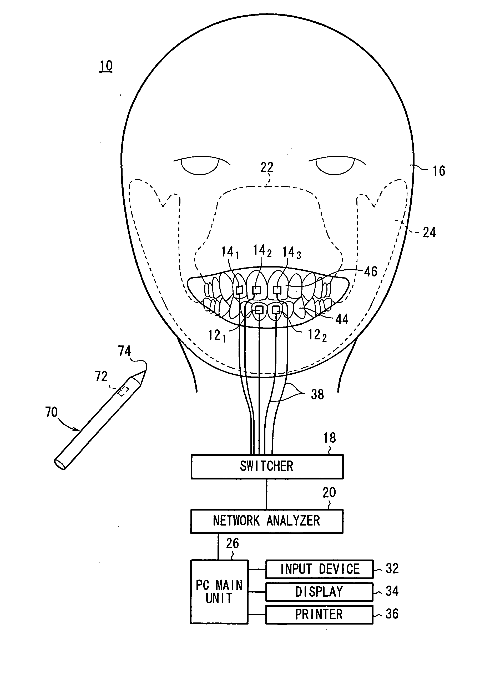
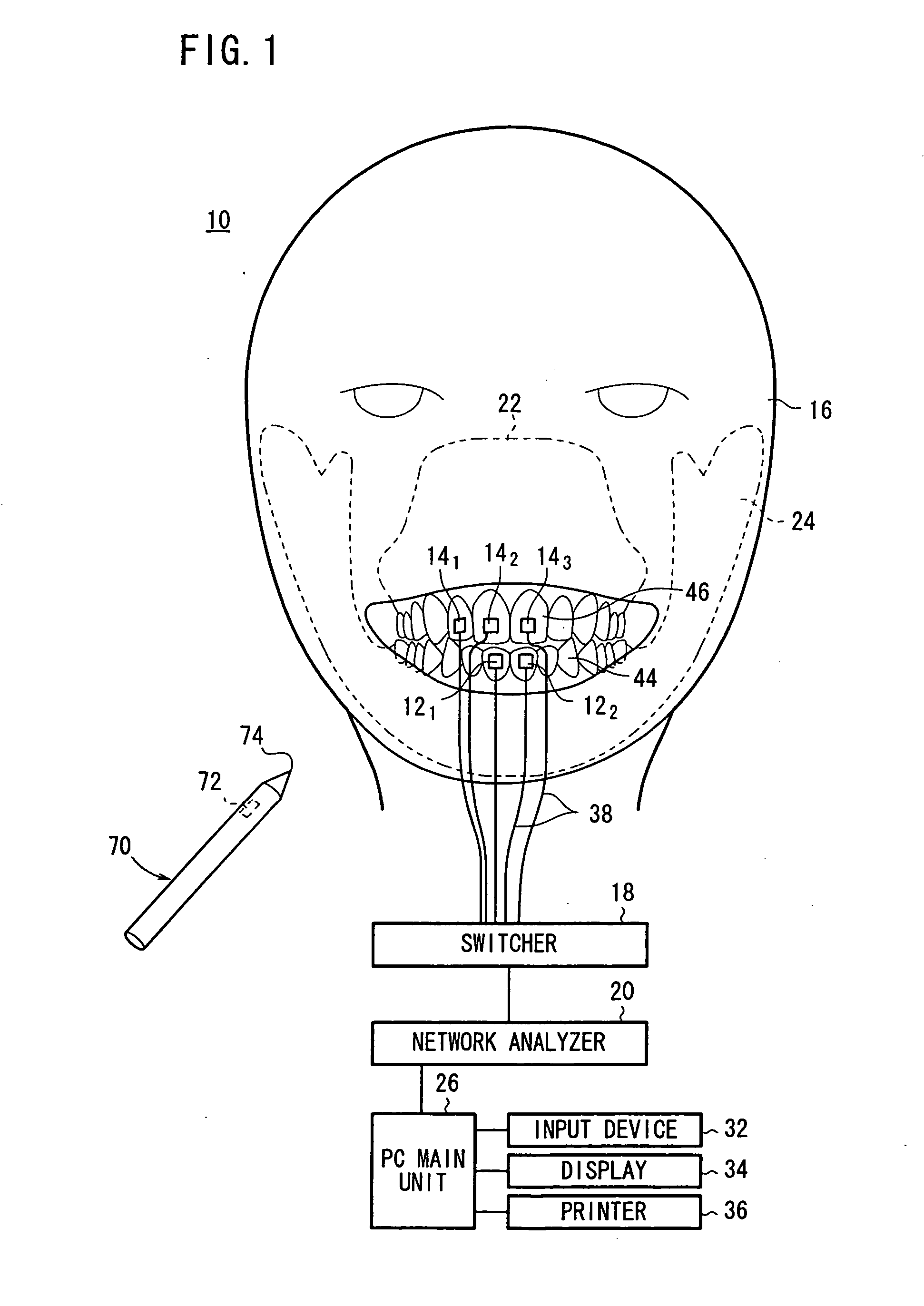
[0057]FIG. 1 is a schematic view showing an arrangement of a three-dimensional jaw movement measuring apparatus 10 according to an embodiment of the present invention.

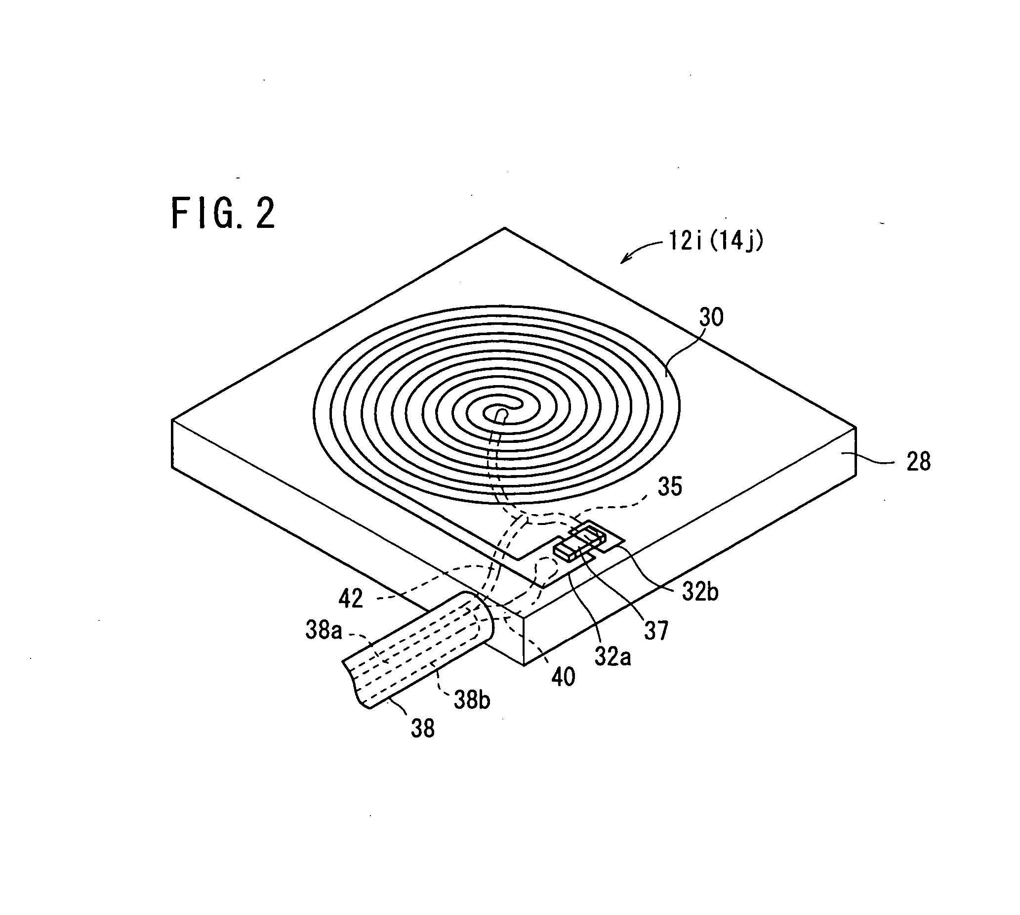
[0058]FIG. 2 is a perspective view of a magnetic generator 12 and a magnetic field sensor 14 of the three-dimensional jaw movement measuring apparatus 10 shown in FIG. 1. FIG. 3 is a perspective view showing the manner in which the magnetic generator 12 and the magnetic field sensor 14 shown in FIG. 2 are applied respectively to given positions on an examinee 16. FIG. 4 is a diagram showing an equivalent circuit of the magnetic generator 12i and the magnetic field sensor 14j shown in FIG. 2.

[0059] As shown in FIGS. 1 through 4, the three-dimensional jaw movement measuring apparatus 10 basically includes a plurality of magnetic generators 12i (i=1, 2 in FIG. 1) attached to given positions on the examinee 16 with an adhesive or the like (not shown), a plurality of magnetic field sensors 14j (j=1 through 3 in FIG. 1) at...


PUM


Abstract

An instrument (10) for measuring three-dimensional motion in a living body comprises a plurality of magnetism generators (12i) fixed to one of at least two objects (44, 46) moving relatively in the living body, a plurality of magnetic field sensors (14j) fixed to the other object in order to perform noncontact detection of the magnetic field of each magnetism generator (12i), and a signal processing means (26) for calculating relative position and direction between each magnetism generator (12i) and each magnetic field sensor (14j) according to a magnetic field detected by each magnetic field sensor (14j). The number of magnetism generators (12i) and magnetic field sensors (14j) is at least five, respectively.

Description

TECHNICAL FIELD [0001] The present invention relates to an apparatus for and a method of measuring three-dimensional movement by installing magnetic generators and magnetic field sensors on at least two relatively movable objects (for example, a combination of at least two of a part in a living body, movable in unison with an upper jaw, a part in a living body, movable in unison with a lower jaw, a tongue, and an artificial tooth mounted in an oral cavity) and measuring relative three-dimensional movement of one of the objects with respect to the other object. BACKGROUND ART [0002] Heretofore, apparatus for measuring three-dimensional movement in a living body have been available in the market. For example, an optical jaw movement measuring apparatus is used to measure relative movement of a lower jaw with respect to an upper jaw, which is constructed integrally with a human head. The optical jaw movement measuring apparatus has a light source device mounted on the head or the upper...

Claims


Application Information

Patent Timeline
IPC IPC(8): G01B7/00A61B5/11A61C19/045
CPCA61B5/1126A61B5/4528A61C19/045A61B5/68A61B5/4547
Inventor ARAI, KENICHIYABUKAMI, SHINKANETAKA, HIROYASU
Owner JAPAN SCI & TECH CORP
Why Eureka
Try Eureka