
Method for measuring temperature of heat pipe

a technology for measuring the temperature of heat pipes and heat pipes, which is applied in the direction of thermometer details, measurement devices, instruments, etc., can solve the problems of high price, time-consuming, and complicated operation of measuring methods, and achieve the effects of reducing thermal contact resistance, improving thermal contact resistance, and reducing cos

Inactive Publication Date: 2007-10-11
JAFFE
View PDF13 Cites 17 Cited by
  • Summary
  • Abstract
  • Description
  • Claims
  • Application Information

AI Technical Summary

Benefits of technology

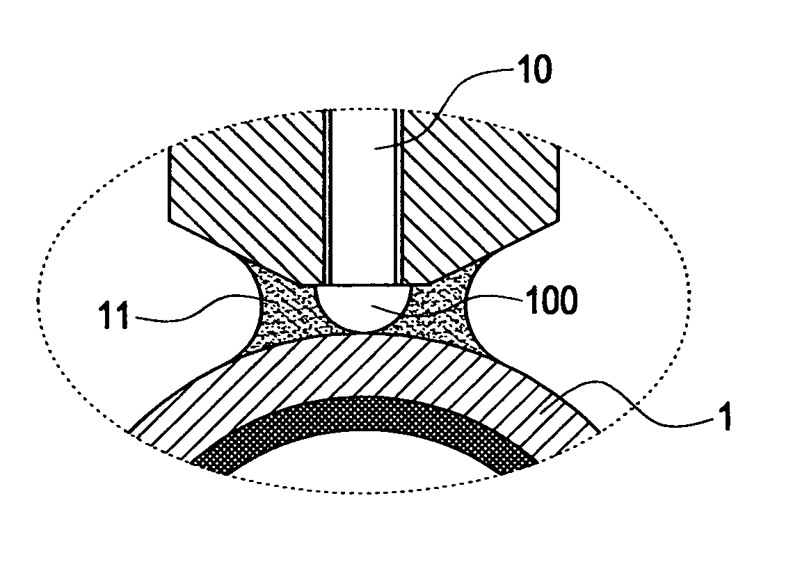
[0007] The present invention is to provide a method for measuring the temperature of a heat pipe. When the thermal couple wire is brought into contact with the surface of the heat pipe, a fluid medium having cohesion, such as water, oil or flowable paste having lower viscosity, is filled therebetween. In this way, when measuring the temperature of the surface of the heat pipe, the stability of the thermal contact resistance can be increased and the thermal contact resistance can be reduced.
[0011] Since the fluid medium can be water, oil or flowable paste having lower viscosity and has cohesion, it can fill the gap between the temperature-sensing head and the surface of the heat pipe. As a result, the stability of the thermal contact resistance between the point-contact of the temperature-sensing head and the heat pipe is increased due to the filling of the fluid medium. Also, the contact effect is greatly enhanced to reduce the thermal contact resistance.

Problems solved by technology

However, since the conventional measuring instruments or apparatuses have some problems, such as high in price, complicated in operation and time-consuming in measurement.
Such a measuring method cannot be applied to all the heat pipes manufactured in mass production, and only some of them can be sampled and measured.
Unfortunately, the glue of the adhesive tapes is liable to remain on surface of the heat pipe 1a.
On the other hand, the heat pipe 1a may be deformed or damaged due to the excessive peeling force, causing the deterioration in the quality of the products.
Further, it also makes the temperature measurement more time-consuming.

Method used


Image

  • Method for measuring temperature of heat pipe
  • Method for measuring temperature of heat pipe
  • Method for measuring temperature of heat pipe

Examples


Embodiment Construction

[0016] In order to make the Examiner better understand the characteristics and the technical contents of the present invention, a detailed description relating to the present invention will be made with reference to the accompanying drawings. However, it should be understood that the drawings are illustrative but not used to limit the scope of the present invention.

[0017]FIG. 2 is a schematic view showing the operation of the present invention, and FIG. 3 is a partially enlarged view showing the portion A in FIG. 2. The present invention provides a method for measuring the temperature of a heat pipe. First, a thermal couple wire 10 is prepared. On end of the thermal couple wire 10 is formed with a temperature-sensing head 100, and the other end thereof is connected to a temperature-sensing device (not shown) for displaying or recording the measured temperature. With the temperature-sensing head 100 of the thermal couple wire 10, the signal of the measured temperature can be transmi...


PUM


Abstract

A method for measuring the temperature of a heat pipe includes the steps of: firstly preparing a thermal couple wire formed at one end thereof with a temperature-sensing head, pressing the temperature-sensing head on the surface of the heat pipe to be measured, and a proper amount of a fluid medium is filled between the temperature-sensing head and the surface of the heat pipe. The fluid medium can be water, oil or flowable paste having lower viscosity. Due to the cohesion of the fluid medium, it can fill the gap between the temperature-sensing head and the surface of the heat pipe. As a result, the stability of the thermal contact resistance between the point-contact of the temperature-sensing head and the heat pipe is increased due to the filling of the fluid medium. Also, the contact effect is greatly enhanced to reduce the thermal contact resistance.

Description

BACKGROUND OF THE INVENTION [0001] 1. Field of the Invention [0002] The present invention relates to a method for measuring the temperature of a heat pipe, and in particular to a method for measuring the temperature of a heat pipe capable of increasing the contact with the surface of the heat pipe when measuring the temperature and reducing the thermal contact resistance. [0003] 2. Description of Prior Art [0004] After heat pipes are completely manufactured, in order to make sure of the quality of the heat pipes manufactured in mass production, each heat pipe should be measured first the capacity of heat transfer to determine whether the expected performance of heat transfer is achieved. However, since the conventional measuring instruments or apparatuses have some problems, such as high in price, complicated in operation and time-consuming in measurement. For example, a thermal couple wire is adhered on the surface of the heat pipe by adhesive tapes. Such a measuring method cannot ...

Claims


Application Information

Patent Timeline
IPC IPC(8): G01K1/08
CPCG01K1/16G01K1/143
Inventor LI, JIA-HAO
Owner JAFFE
Learn More