
Fuel cell system

a fuel cell and system technology, applied in the direction of fuel cells, reactant parameter control, electrical apparatus, etc., can solve the problems of difficult space and cost saving, and achieve the effect of convenient maintenance of the fuel cell

Inactive Publication Date: 2007-09-27
SANYO ELECTRIC CO LTD
View PDF3 Cites 14 Cited by
  • Summary
  • Abstract
  • Description
  • Claims
  • Application Information

AI Technical Summary

Benefits of technology

[0008]A general purpose of the present invention is to provide a fuel cell system in which user maintenance of a DMFC is facilitated without increasing the complexity of structure of the fuel cell system.
[0010]According to this embodiment, users can easily perform maintenance of the fuel cell system merely by changing cartridges.
[0015]According to this embodiment, users can easily define a selection of passages in the fuel cell system optimal for the type of cartridge, merely by changing cartridges. As a result, users can easily perform maintenance of the fuel cell.

Problems solved by technology

Meanwhile, if user convenience is pursued too much and the structure of the fuel cell system becomes complicated as a result, it would be difficult to save space and cost.

Method used


Image

  • Fuel cell system
  • Fuel cell system
  • Fuel cell system

Examples


Embodiment Construction

[0028]The invention will now be described by reference to the preferred embodiments. This does not intend to limit the scope of the present invention, but to exemplify the invention.

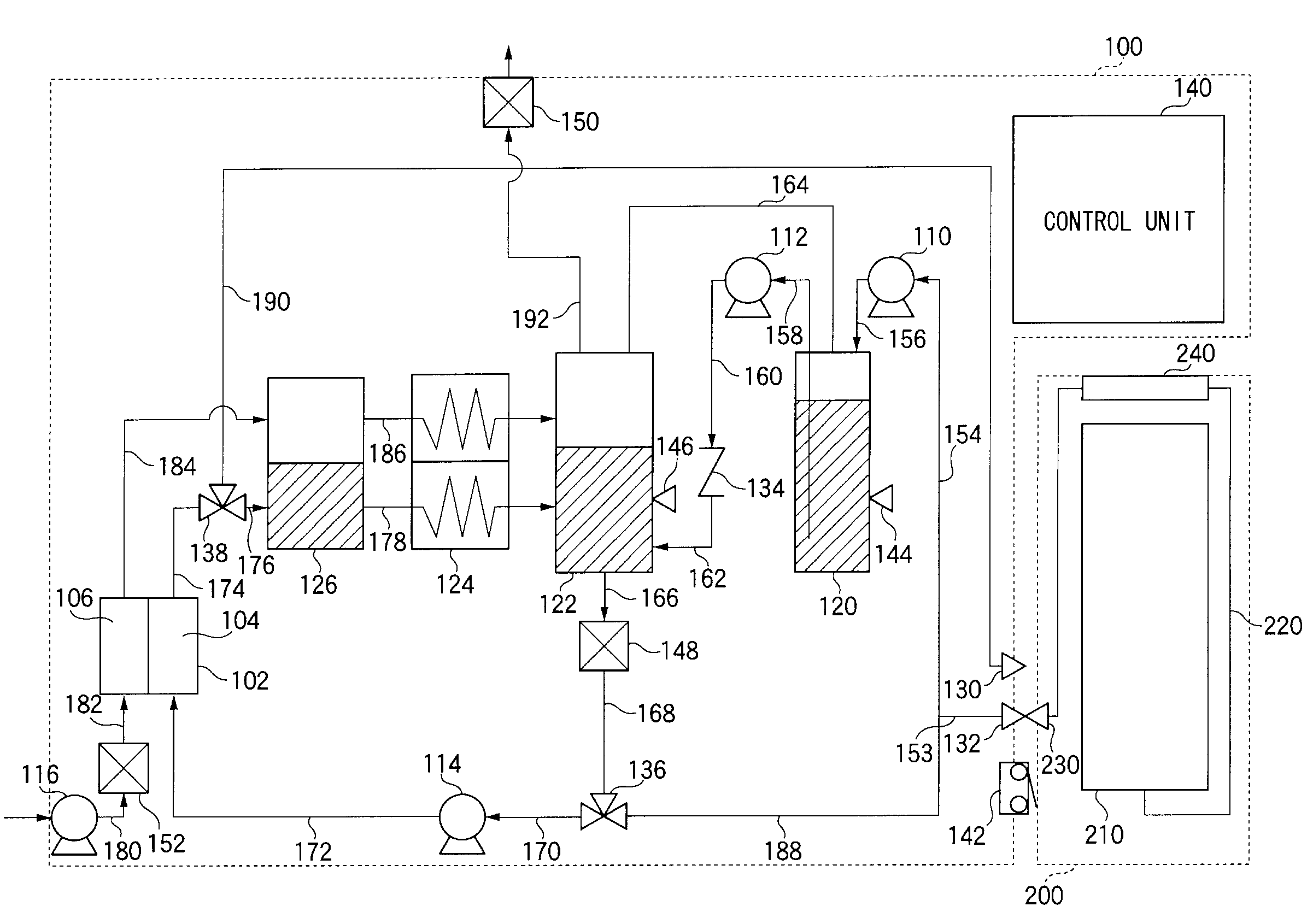
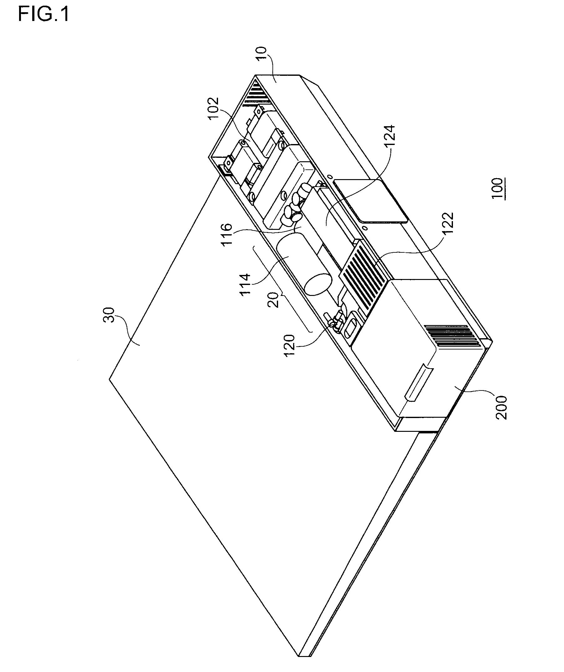
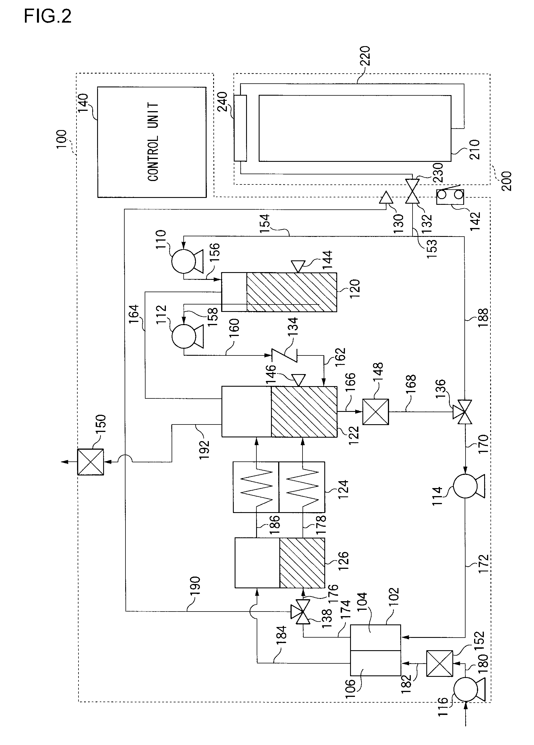
[0029]FIG. 1 is a perspective view of a fuel cell system 100 according to an embodiment of the present invention, and FIG. 2 illustrates the structure of the fuel cell system 100. The fuel cell system 100 uses methanol as a liquid fuel. This system 100 is a direct methanol fuel cell (DMFC) system which generates electric power in a fuel cell by an electrochemical reaction induced between the methanol and air as an oxidant. The system 100 is compact in overall size so that it can be suitably used as a power supply for a portable notebook personal computer.

[0030]The fuel cell system 100 is structured such that inside a casing 10 as shown in FIG. 1 is mounted a fuel cell 102 on one side thereof in a longitudinal direction. A fuel cartridge 200 connected detachably with the fuel cell system 100 is mounted on...


PUM

PropertyMeasurementUnit
poweraaaaaaaaaa
concentrationaaaaaaaaaa
thermal energyaaaaaaaaaa

Abstract

A fuel cell system includes a fuel cell, a fuel tank, a first passage which supplies liquid fuel from the fuel tank to the fuel cell, a cartridge holder in which a plurality of types of cartridges are replaceably loaded, a second passage which supplies the content discharged from the cartridge to the fuel cell, a cartridge detector which detects the type of cartridge loaded in the cartridge holder, and a passage control means which controls the passages in accordance with the type of cartridge detected.

Description

BACKGROUND OF THE INVENTION[0001]1. Field of the Invention[0002]The present invention relates to a fuel cell system and, more particularly, to a technology for changing the passages in the fuel cell system in accordance with the type of cartridge loaded.[0003]2. Description of the Related Art[0004]A fuel cell is a device that generates electricity from hydrogen and oxygen so as to obtain highly efficient power generation. A principal feature of a fuel cell is its capacity for direct power generation which does not undergo a stage of thermal energy or kinetic energy as in conventional power generation. This presents such advantages as high power generation efficiency despite the small scale setup, reduced emission of nitrogen compounds and the like, and environmental friendliness on account of minimal noise or vibration.[0005]Of various types of fuel cells, a polymer electrolyte fuel cell excels in its low operating temperature and high output density. Recently, direct methanol fuel ...

Claims


Application Information

Patent Timeline
Patent Type & Authority Applications(United States)
IPC IPC(8): H01M8/04
CPCH01M8/04186H01M8/04208H01M8/04313H01M8/0444H01M8/04447H01M8/04559Y02E60/523H01M8/04753H01M8/04798H01M8/04805H01M8/04955H01M8/1011H01M8/04686Y02E60/50H01M8/04H01M8/06
Inventor FUJITA, GOROKIBUNE, KENJIIMURA, SHINICHIROKABUMOTO, HIROKI
Owner SANYO ELECTRIC CO LTD
Learn More