
Basalt particle-containing articles for ballistic shield mats/tiles/protective building components

a technology of ballistic shield mats/tiles/protective building components and base particles, which is applied in the field of base particle-containing composite compositions, can solve the problems of inability to protect against multiple projectiles, unsuitable armor for light vehicles such as automobiles, jeeps, light boats, etc., and achieve the effect of light weight and low bulk

Inactive Publication Date: 2007-09-27
U S WIND FARMING
View PDF12 Cites 31 Cited by
  • Summary
  • Abstract
  • Description
  • Claims
  • Application Information

AI Technical Summary

Benefits of technology

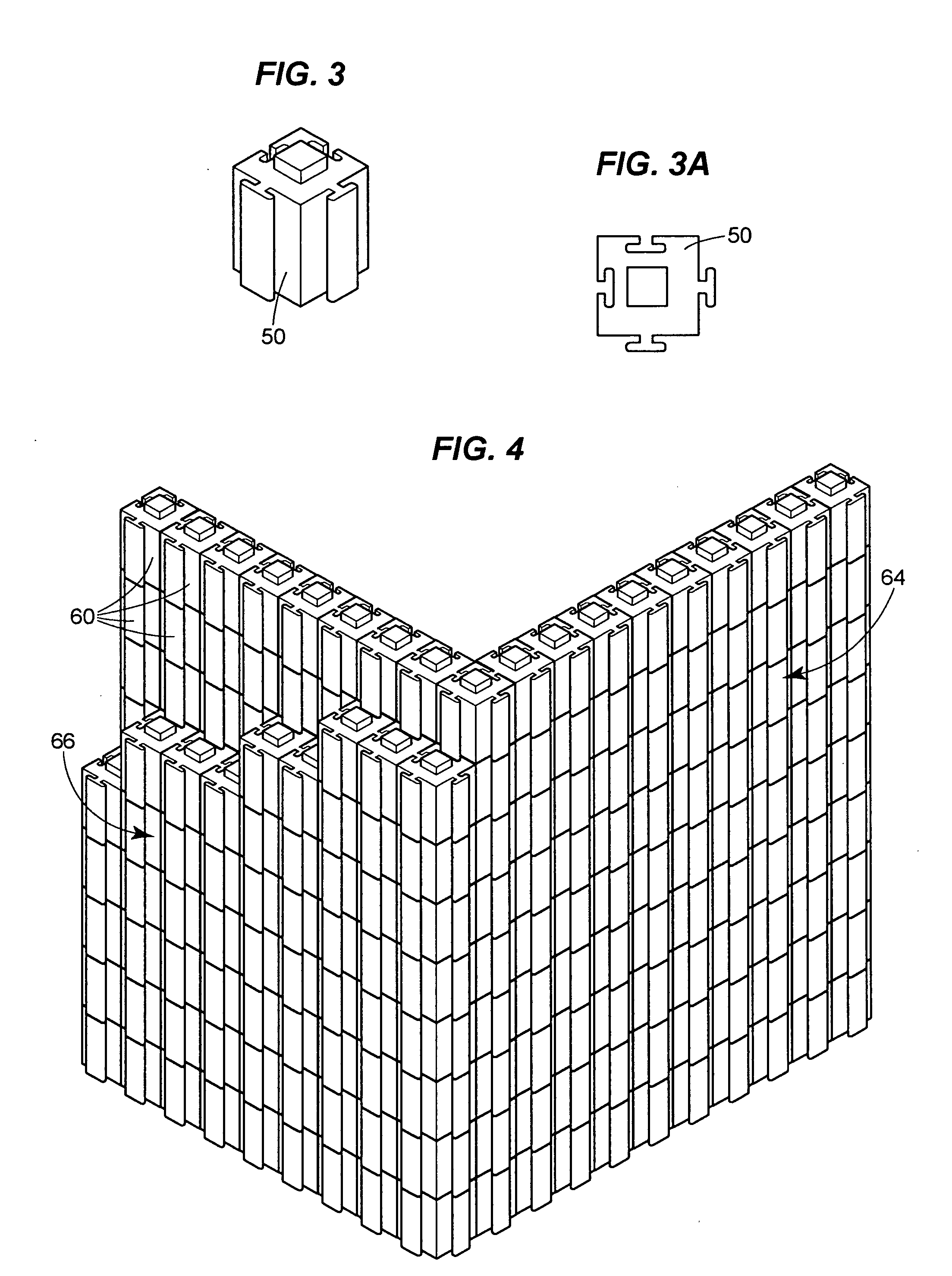
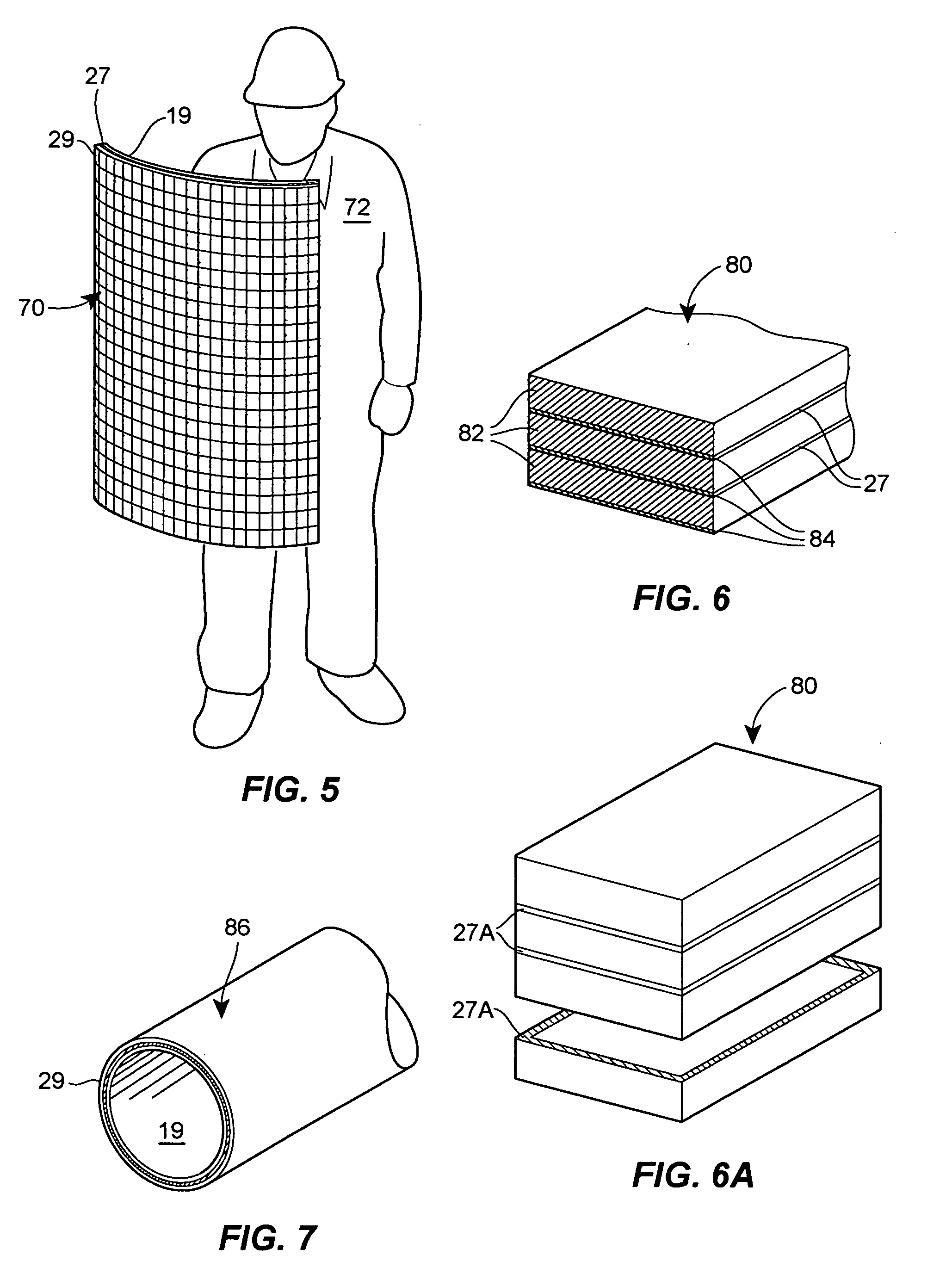
[0016] One aspect of the basalt particle-containing compositions, articles, methods, building components and panels described herein is to provide multiple, spaced armor mats, panels or building blocks that include spaced, parallel walls and that can be manufactured in a desired shape and size, and which are particularly effective in arresting a plurality of projectiles impacting upon the same general area of the manufactured article that contains multiple, spaced layers of basalt particles bound by a binder. In another embodiment, the basalt particles are bound in adjacent, but spaced layers, or in multiple mats / panels that are joined together, sandwiching air or a deformable spacing member therebetween.

Problems solved by technology

Due to its weight, such armor is quite unsuitable for light vehicles such as automobiles, jeeps, light boats, or aircraft, whose performance is compromised by steel panels having a thickness of more than a few millimeters.
Ceramic shields, however, shatter when struck by a fast moving projectile and, therefore, cannot protect against multiple projectiles that strike in close proximity, as occurs with automatic weapons fire.
Much research has been devoted to improving the low tensile and low flexible strength and poor fracture toughness of ceramic materials; however, these remain the major drawbacks to the use of ceramic plates and other large components which can crack and / or shatter in response to the shock of incoming projectiles.
One disadvantage of this type of panel is that on completion, the panels are almost impossible to modify.
In use, the ceramic coating performs well against the first bullet, but tends to shatter, and thus fails to protect against further projectiles.
Such clothing is certainly valuable against low energy projectiles, such as those fired from a distance of several hundred meters, but fails to protect the wearer against high-velocity projectiles originating at closer range.
If made to provide such protection, the weight and / or cost of such clothing discourages its use.
A further known problem with such clothing is that even when it succeeds in stopping a projectile, the user may suffer injury due to indentation of the vest to the body, caused by too small a body area being impacted and the inability to absorb the energy of a bullet.
A common problem with prior art ceramic armor concerns damage inflicted on the armor structure by a first projectile, whether stopped or penetrating.
Such damage weakens the armor panel, and so allows penetration of a following projectile.

Method used


Image

  • Basalt particle-containing articles for ballistic shield mats/tiles/protective building components
  • Basalt particle-containing articles for ballistic shield mats/tiles/protective building components
  • Basalt particle-containing articles for ballistic shield mats/tiles/protective building components

Examples


example 1

[0119] One manufacturing process for the manufacture of a handmade, basalt particle-containing plate or panel is as follows:

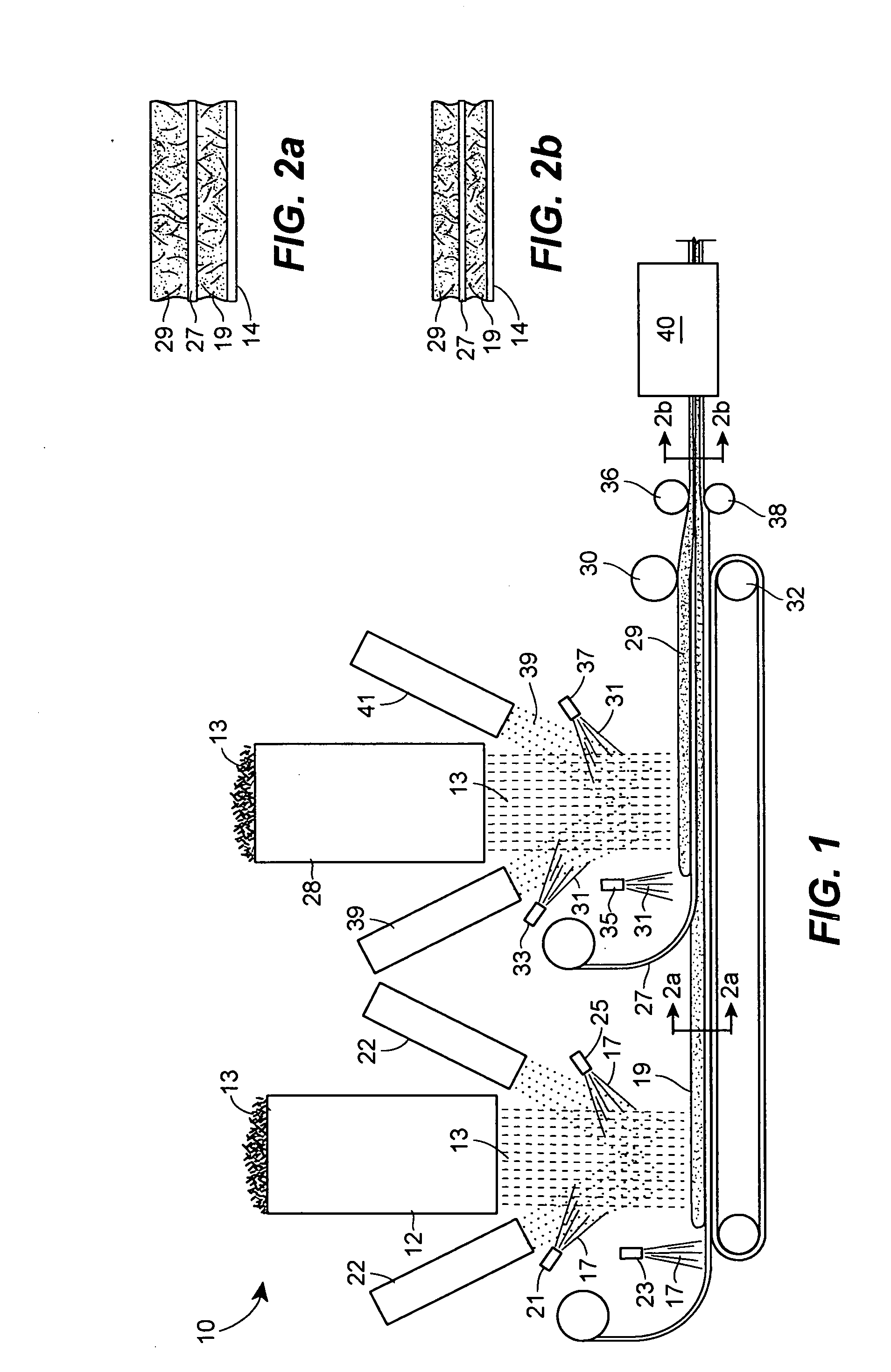
[0120] A homogeneous layer of basalt infused (20% by weight basalt powder) polyester resin was brushed onto a waxed, flat mold surface. One (1) layer of a 1½ oz. chopped strand fiberglass, non-woven mat having a silane binder was then applied over the basalt / resin composition. The following layers are alternated: (1) a non-woven fiberglass mat, (2) 24 oz. woven fiberglass roving, (3) non-woven fiberglass mat, (4) 24 oz. woven fiberglass roving, etc., with a coating of basalt / resin composition brushed onto each applied fiberglass layer. The first fiberglass layer is a mat to achieve a smooth surface finish. After applying five non-woven mats and three woven roving layers, or ⅜″ thickness, the laminated product (resin) is allowed to cure. The plate or sheet is then popped off the mold and trimmed with a jig saw or skill saw. The basalt / resin coating composition ...

example 2

Spaced, Multi-Layer Conduit Manufacturing

[0133] Spiral wrap a 6″ wide 10 mil. thick Mylar film over a rotating steel mandrel. Wrap a 2″ wide ½″ thick foam collar onto one end of the mandrel. Wet the mandrel with the basalt particle-containing resin with a mandrel brush. Spiral alternating layers of 1½ oz.×6″ wide non-woven chopped fiberglass strand mat and followed by 6″ wide×24 oz. woven fiberglass roving, wetting each layer with the basalt particle-containing resin. Leave approximately ⅛″ between edges of each 1½ oz. mat for stretching when wet. Roll each layer with a grooved aluminum roller as the mandrel turns to remove entrapped air. Start and finish with 1½ oz fiberglass non-woven mat for better, smoother surface finish. After five (5) layers of non-woven fiberglass mat and three (3) layers of woven fiberglass roving have been applied to the mandrel, let the mandrel continue to rotate for faster resin solvent evaporation until the resin reaches the gel stage, then turn off th...


PUM

PropertyMeasurementUnit
particle sizeaaaaaaaaaa

Abstract

A spaced, multi-layer article of manufacture comprising a first layer comprising about 10% to about 80% by weight basalt particles, about 2% to about 50% by weight reinforcing fibers, and about 5% to about 50% by weight of an adhesive resin binder; a second layer comprising about 10% to about 80% by weight basalt particles, about 2% to about 50% by weight reinforcing fibers, and about 5% to about 50% by weight of an adhesive resin binder; and an intermediate spacing layer that separates the first and second layers.

Description

FIELD OF THE INVENTION [0001] The present invention is directed to basalt particle-containing composite compositions, and methods of manufacture. It has been found that basalt particles, when combined with a resin binder and a reinforcing material, such as fiberglass, provide unexpected shielding results for ballistic armor / shields; fire-retardant, self-extinguishing building panels; construction blocks and protective coatings on substrates. The armor panels can be worn, as in a bullet-proof vest, or can be used as a shield to protect a vehicle, aircraft or other structures as projectile penetration-resistant and fire-retardant materials. BACKGROUND AND PRIOR ART [0002] Basalt is an igneous mineral ore that can be melted and formed into continuous fibers, staple fibers, e.g., 30 mm in length, micro fibers of, for example, 0.42 μm in diameter, and intermediate lengths and diameters. Basalt fibers have been (a) used to make papermaking fabric, see U.S. Pat. No. 6,926,221; (b) zirconia...

Claims


Application Information

Patent Timeline
Patent Type & Authority Applications(United States)
IPC IPC(8): B32B7/02
CPCB32B5/26Y10T428/24942B32B27/04B32B27/18F41H5/0414F41H5/08B32B5/12B32B5/16B32B5/18B32B5/30B32B3/06B32B2260/025B32B2260/046B32B2262/0269B32B2262/10B32B2262/101B32B2262/105B32B2264/107B32B2266/0228B32B2266/025B32B2266/0271B32B2266/0278B32B2307/3065B32B2307/558B32B2419/00B32B2571/02B32B2597/00B32B2605/08B32B2605/18B32B2607/00B32B17/02
Inventor TELANDER, WILLIAM
Owner U S WIND FARMING
Learn More