
Flexible Template-Directed Microporous Partially Pyrolyzed Polymeric Membranes

a polymer membrane, partially pyrolyzed technology, applied in the direction of membranes, separation processes, membranes, etc., can solve the problems of inorganic membrane technology, limited in a number, new membrane materials with better separation performance still need to be developed, etc., to achieve high permeability in gas separation, improve selectivity, and improve the effect of permeability

Inactive Publication Date: 2007-09-13
UOP LLC
View PDF59 Cites 39 Cited by
  • Summary
  • Abstract
  • Description
  • Claims
  • Application Information

AI Technical Summary

Benefits of technology

[0010]The membranes described in this invention have greatly increased selectivities and reasonably high permeabilities in separation of gases, good resistance to plasticization by CO2 or hydrocarbons such as C3H6, increased thermal stability, enhanced chemical resistance, maintained flexibility and mechanical strength compared to their precursor polymeric membranes.

Problems solved by technology

To compare with conventional separation processes, however, new membrane materials with better separation performance still need to be developed due to the limitations of currently available membrane materials including both organic polymeric and inorganic materials.
Although these polymeric materials have many advantages, they are limited in a number of properties including selectivity, permeability, plasticization issue, chemical and thermal stabilities.
The main challenges are: achieving higher selectivity with acceptable productivity and maintaining these properties in the presence of complex and aggressive feeds.
However, the challenges faced by current inorganic membrane technology are: high cost, poor processability, and poor mechanical strength.

Method used


Image

  • Flexible Template-Directed Microporous Partially Pyrolyzed Polymeric Membranes
  • Flexible Template-Directed Microporous Partially Pyrolyzed Polymeric Membranes
  • Flexible Template-Directed Microporous Partially Pyrolyzed Polymeric Membranes

Examples


Embodiment Construction

[0018]In principle, membrane-based technologies have the advantages of both low capital cost and high-energy efficiency compared to conventional separation methods. Polymeric membranes have been proven to operate successfully in industrial gas separations. To combine high selectivity and high permeability together with high thermal stability, new high-performance polymers such as polyimides (PIs), poly(trimethylsilylpropyne) (PTMSP), and polytriazole were developed. These new polymeric membrane materials have shown promising properties for separation of gas pairs such as CO2 / CH, O2 / N2, H2 / CH4, and C3H6 / C3H8. However, current polymeric membrane materials have reached a limit in their productivity-selectivity trade-off relationship. In addition, polymeric membranes have a plasticization problem in the presence of condensable gases such as CO2 or C3H6. Plasticization of the polymer is represented by the membrane structure swelling and by a significant increase in the permeabilities of ...


PUM

PropertyMeasurementUnit
Temperatureaaaaaaaaaa
Pressureaaaaaaaaaa
Pressureaaaaaaaaaa

Abstract

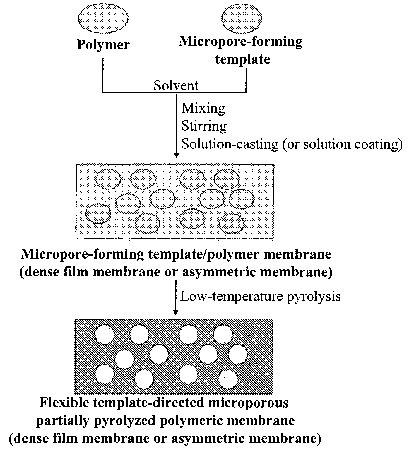
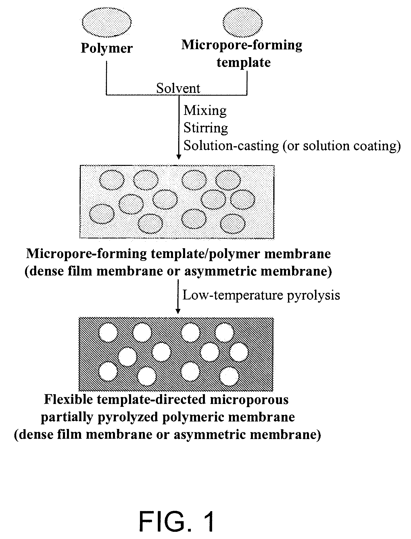
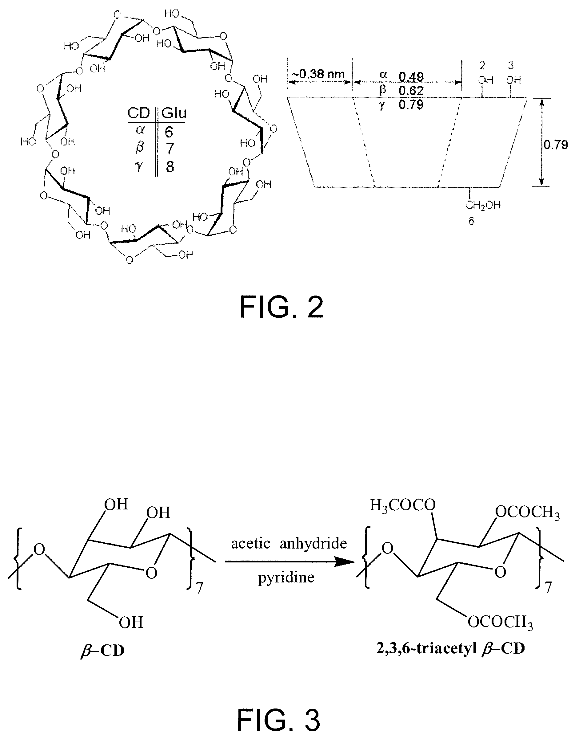
This invention describes a new concept of flexible template-directed microporous partially pyrolyzed polymeric membranes which have greatly improved performance in separation of gas pairs compared to their precursor polymeric membranes. Organic hosts, such as crown ethers, cyclodextrins (CDs), calixarenes (CXs), and spherands, or polymeric additives, such as poly(ethylene glycol) (PEG) and polyvinylpyrrolidone (PVP) were used as the micropore-forming templates. Micropore-forming template / polymer blend membranes comprising organic micropore-forming templates embedded in a polymer matrix were prepared by dissolving the organic micropore-forming templates in the polymer solution followed by solution-casting and solvent evaporation or solvent exchange. Low-temperature selectively pyrolyzing micropore-forming templates in the micropore-forming template / polymer blend membranes at a nitrogen flow resulted in the formation of flexible microporous partially pyrolyzed polymeric membranes.

Description

CROSS-REFERENCE TO RELATED APPLICATION[0001]This application claims priority from Provisional Application Ser. No. 60 / 781,289 filed Mar. 10, 2006, the contents of which are hereby incorporated by reference.BACKGROUND OF THE INVENTION[0002]This invention pertains to a new concept of flexible template-directed microporous partially pyrolyzed polymeric membranes. More specifically, this invention pertains to a method for producing flexible microporous partially pyrolyzed polymeric membranes using organic hosts, such as crown ethers, cyclodextrins (CDs), calixarenes (CXs), and spherands, or polymeric additives, such as poly(ethylene glycol) (PEG) and polyvinylpyrrolidone (PVP) as micropore-forming templates. Selectively pyrolyzing micropore-forming templates in the micropore-forming template / polymer blend membranes at low-temperature resulted in the formation of flexible microporous partially pyrolyzed polymeric membranes. This invention also pertains to the application of the described...

Claims


Application Information

Patent Timeline
IPC IPC(8): B01D53/22
CPCB01D53/228B01D67/003Y02C10/10B01D2323/08B01D2323/24B01D71/64Y02C20/40B01D2323/081
Inventor LIU, CHUNQINGLESCH, DAVID A.WILSON, STEPHEN T.
Owner UOP LLC
Learn More