Eureka AIR delivers breakthrough ideas for toughest innovation challenges, trusted by R&D personnel around the world.

Anti-glare glass substrate

a technology of glass substrate and glare reduction, which is applied in the direction of optical elements, instruments, transportation and packaging, etc., can solve the problems of uneven scattering of display light rays outputted by the lcd device, dispersion of light rays on each pixel, etc., and achieves excellent visibility and smooth writing of information thereon.

Inactive Publication Date: 2007-08-23
CENT GLASS CO LTD
View PDF6 Cites 59 Cited by
  • Summary
  • Abstract
  • Description
  • Claims
  • Application Information

AI Technical Summary

Benefits of technology

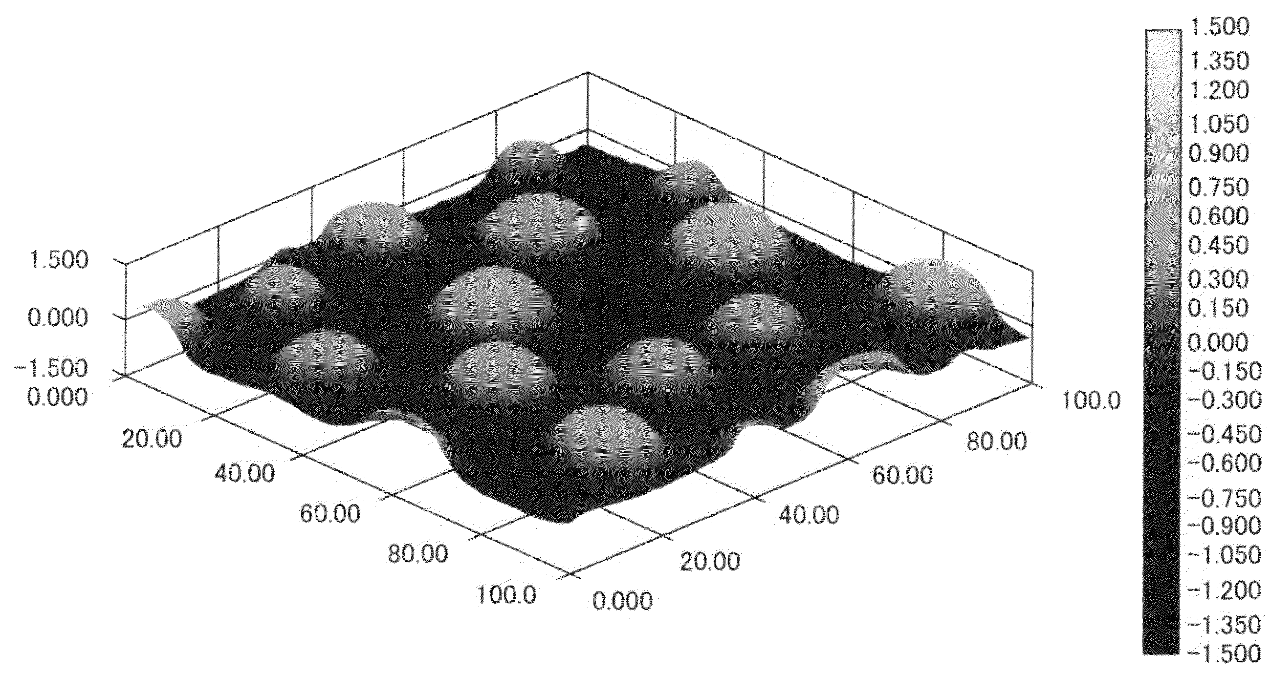
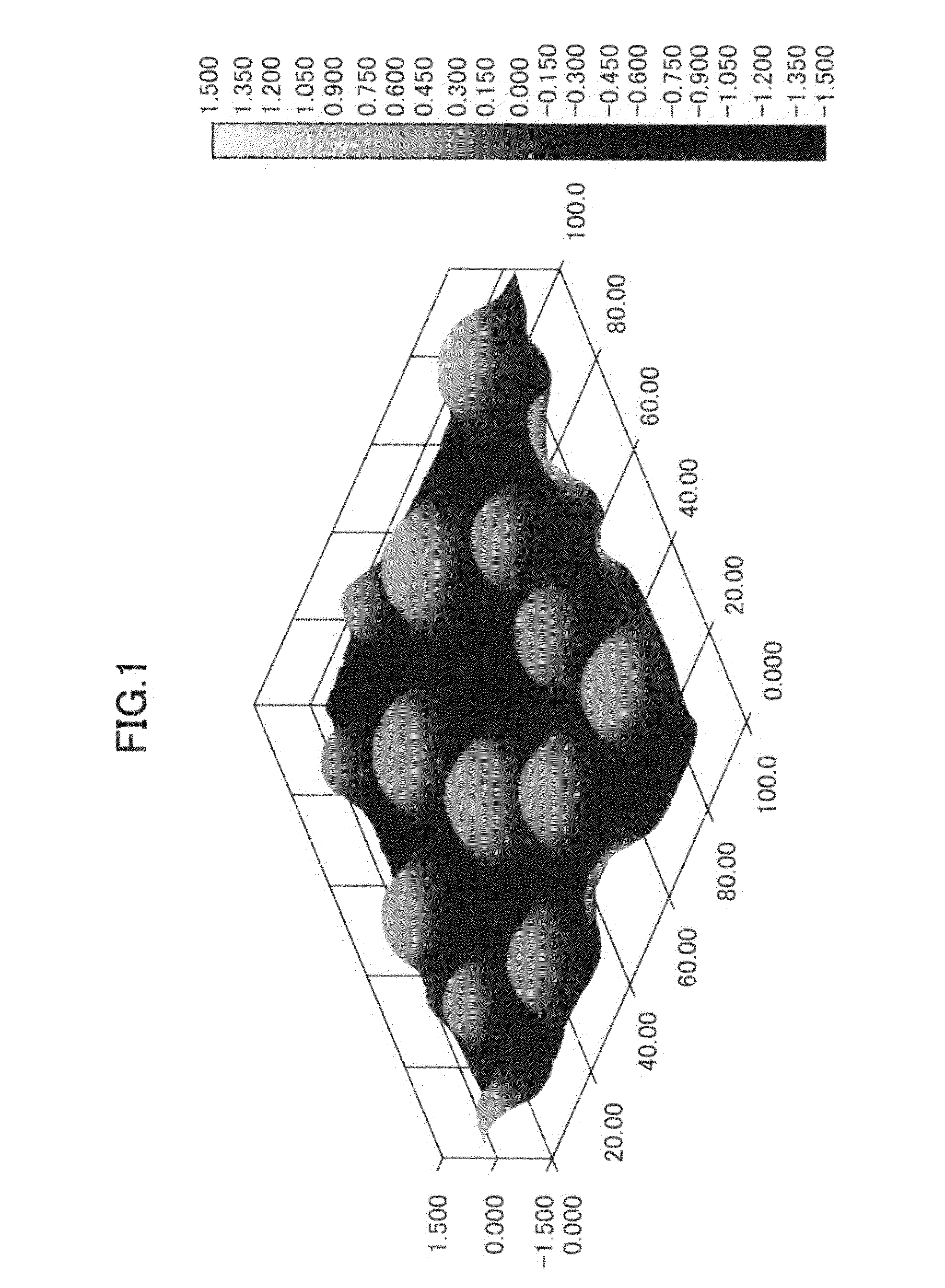
[0028]In the anti-glare glass substrate according to the present invention, the projection bodies preferably having a fine small hill-like shape would ensure a desired anti-glare effect. Moreover, the scattering of light rays by the projection bodies is uniform for respective sections each having an area corresponding to that of the pixel of an LCD device and accordingly, there is not observed any partial iridescence resulted from the interference upon using the same for the purpose of anti-glaring an LCD device and it can ensure an excellent visibility. In addition, when using the anti-glare glass substrate having a preferred shape according to the present invention as a cover glass for a pen-input device, the effects such as those described below will be accomplished: the cover glass can ensure an ability to smoothly write information thereon with a pen without causing any scratch-feeling.

Problems solved by technology

However, the conventional anti-glaring treatments have been developed only on the basis of such a technical idea that the interested surface is roughened and therefore, the height of uneven shape and the depth thereof observed at each particular position are randomly distributed from position to position.
Although the uneven structure of the surface would ensure an anti-glare function thereof, the unevenness likewise scatters the display light rays outputted from the LCD device.
This in turn results in the dispersion in the quantity of light rays scattered on each pixel and accordingly, the user of the device would observe a partial iridescence generated through the interference.

Method used


Image

  • Anti-glare glass substrate
  • Anti-glare glass substrate
  • Anti-glare glass substrate

Examples


example 1

1. Preparation of Coating Liquid for Forming Anti-Glare Coating

Preparation of Silica Sol (A):

[0076]Tetraethoxy-silane (Si(OC2H5)4) was used as a starting alkoxide, water for hydrolysis was added thereto so that the molar ratio: water / alkoxide was adjusted to 8, nitric acid as an acid catalyst was likewise added to the starting alkoxide so as to adjust the molar ratio: nitric acid / water to 0.01 and ethanol as a solvent was added thereto in such a manner that the solid content of the reaction solution was set at a level of 9% by mass as expressed in terms of the concentration converted into that of SiO2, after the completion of the hydrolysis. The resulting mixed liquid was hydrolyzed and / or polycondensed by stirring the same at room temperature over 24 hours to thus give Silica Sol (A). The resulting Silica Sol (A) was found to have a number average molecular weight of 613.

Preparation of Silica Sol (B):

[0077]Phenyl triethoxy-silane (C6H5Si(OC2H5)3) was used as a starting alkoxide, wa...

example 2

[0084]The same procedures used in Example 1 were repeated except that the heating temperature after the completion of the coating operation was changed to 650° C. to thus prepare an anti-glare glass substrate. The results obtained in the observation of the coating surface are shown in FIG. 2. There were observed projection bodies on an approximately planar surface, but these projection bodies were not small hill-like projected bodies having a tip at the center thereof such as those observed for the anti-glare glass substrate prepared in Example 1, but small hill-like projection bodies whose central portion is depressed. The coating formed on the anti-glare glass substrate thus prepared was inspected for a variety of characteristic properties such as the surface roughness, the distribution density of the depressed portions per unit area, the 60-deg. relative-specular glossiness, the partial iridescence generated due to interference, the outward appearance of images displayed on LCD a...

example 3

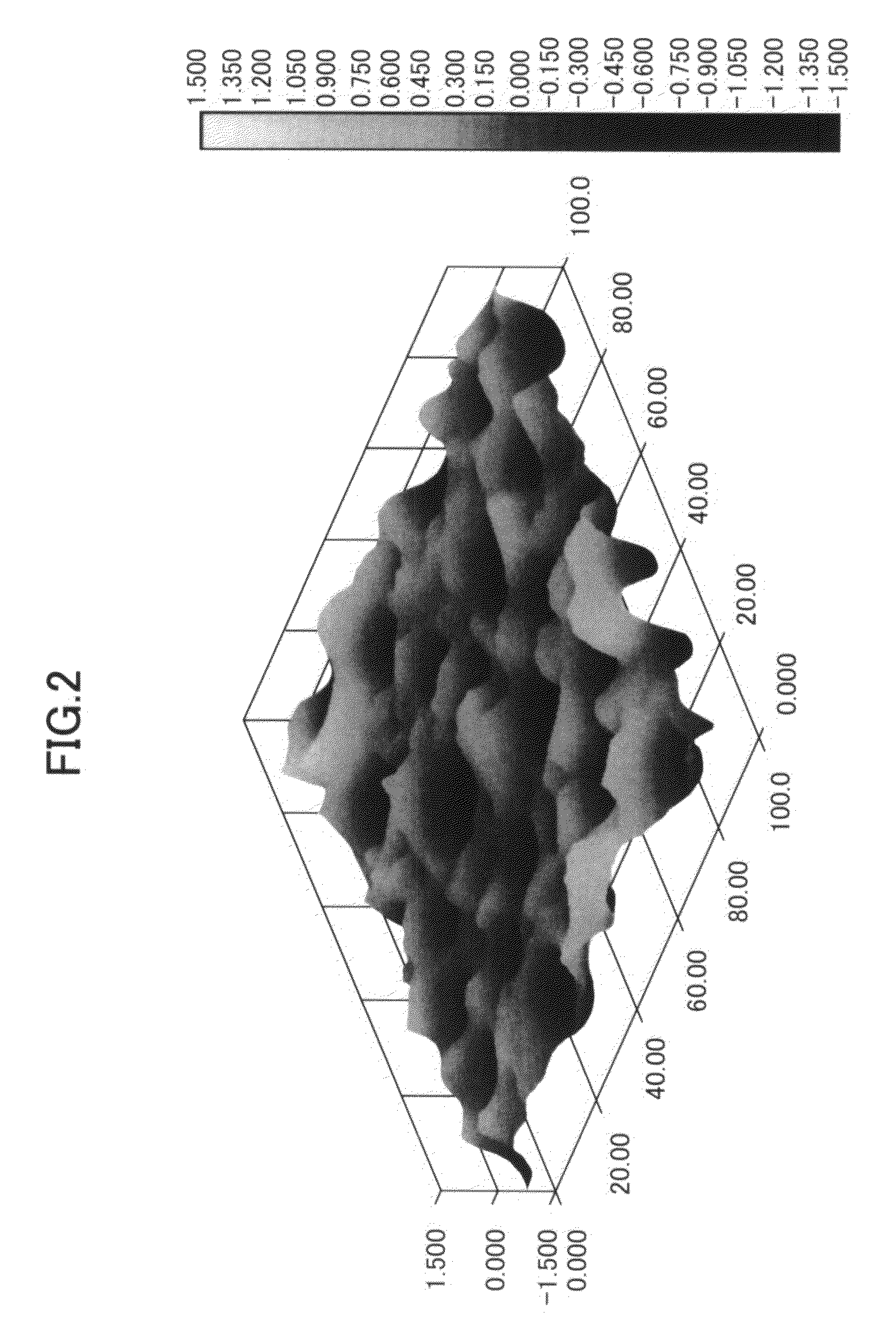
[0085]The same procedures used in Example 1 were repeated except that Silica Sol (A) and Silica Sol (B) were blended together in a mixing ratio (by mass): Silica Sol (A) Silica Sol (B) of 2:1 and that the addition of Silica Sol (C) was omitted, to thus prepare an anti-glare glass substrate. The results obtained in the observation of the anti-glare coating thus prepared are shown in FIG. 3. Although fine cracks were formed on the coating between the neighboring projection bodies, there was observed a pattern of projection bodies formed on an approximately planar surface resulted from the bi-nodal phase separation.

[0086]The anti-glare thin film thus formed was inspected for a variety of characteristic properties such as the surface roughness, the distribution density of the projection bodies per unit area, the 60-deg. relative-specular glossiness, the partial iridescence generated due to interference, and the coating hardness. The results thus obtained are summarized in the foregoing ...


PUM

PropertyMeasurementUnit
Temperatureaaaaaaaaaa
Lengthaaaaaaaaaa
Areaaaaaaaaaaa

Abstract

An anti-glare glass substrate used for liquid crystal display devices is disclosed, which comprises a glass substrate; and a coating covering one side of said substrate, the coating having, on its surface, projection bodies which have round bottom surfaces and have an average bottom surface area ranging from 80 to 400 μm2, the projection bodies being randomly arranged on said coating at a density of 5 or more projection bodies per an area equivalent to one pixel of the liquid crystal display device, and the coating having a surface roughness from 0.1 to 0.4 μm. The anti-glare glass substrate can be prepared by the steps of (1) preparing a coating liquid by blending a silica sol (A) consisting of an oligomer whose crosslinks are formed from [SiO4 / 2] as crosslinking units and whose number average molecular weight ranges from 300 to 1000 (polystyrene conversion) and a silica sol (B) consisting of an oligomer in which silicon oxides having bonds between aryl groups and silicon atoms are formed as crosslinking units and whose number average molecular weight ranges from 500 to 1000 (polystyrene conversion); and (2) applying the resulting coating liquid onto the surface of a glass substrate according to the spin coating technique.

Description

TECHNICAL FIELD OF THE INVENTION[0001]The present invention relates to an anti-glare (or glare-reducing) glass substrate for imparting anti-glare characteristic properties to a liquid crystal display device, as well as a method for preparing the same. In addition, the present invention relates to an anti-glare glass substrate for liquid crystal display devices, which can easily be washed, as well as a method for preparing the same.TECHNICAL BACKGROUND OF THE INVENTION[0002]The liquid crystal display (LCD) device has been used in the display panels for use in a display device comprising a device for data-inputting such as a data-tablet plate. The device can not only input letters, patterns or the like through hand-writing operations using a data input device such as a data-inputting pen, but also can display the contents thus inputted on a display panel. As an example of the device, there can be mentioned a pen input device and touch panel device.[0003]In addition, it has been desire...

Claims


Application Information

Patent Timeline
IPC IPC(8): G02B27/00C09K19/00
CPCC03C1/008C03C17/007C03C17/009C03C2217/213Y10T428/1086C03C2217/478C03C2217/77C03C2218/113G02B1/11C03C2217/42C09K2323/06
Inventor TSUDA, YASUTAKATANAKA, KATSUTO
Owner CENT GLASS CO LTD
Why Eureka
Eureka Blog
Learn More