
Method of depositing Ru films having high density

a technology of ruthenium film and high density, which is applied in the direction of instruments, sports apparatus, and semiconductor/solid-state device details. it can solve the problems of uneven formation of ruthenium film in narrow, deep structure by cvd method, and inability to form ruthenium film on metal oxide layer, etc., and achieve high density, high deposition speed, excellent step coverage

Active Publication Date: 2007-08-16
ASM KOREA LTD
View PDF8 Cites 284 Cited by
  • Summary
  • Abstract
  • Description
  • Claims
  • Application Information

AI Technical Summary

Benefits of technology

[0021]One embodiment provides a ruthenium film deposition method that is capable of depositing a ruthenium film having excellent step coverage and a high density at a high deposition speed. Another embodiment provides a ruthenium film having excellent step coverage and a high density. Yet another embodiment provides a ruthenium film deposition method that is capable of depositing a ruthenium film having a high density at a high deposition speed without oxidation of an underlying layer.

Problems solved by technology

However, a ruthenium film may not be formed uniformly in a narrow, deep structure by the CVD method.
However, the ruthenium film may not be formed on a metal oxide layer such as SiO2, Al2O3, HfO2, and ZrO2 immediately by the thermal ALD method.
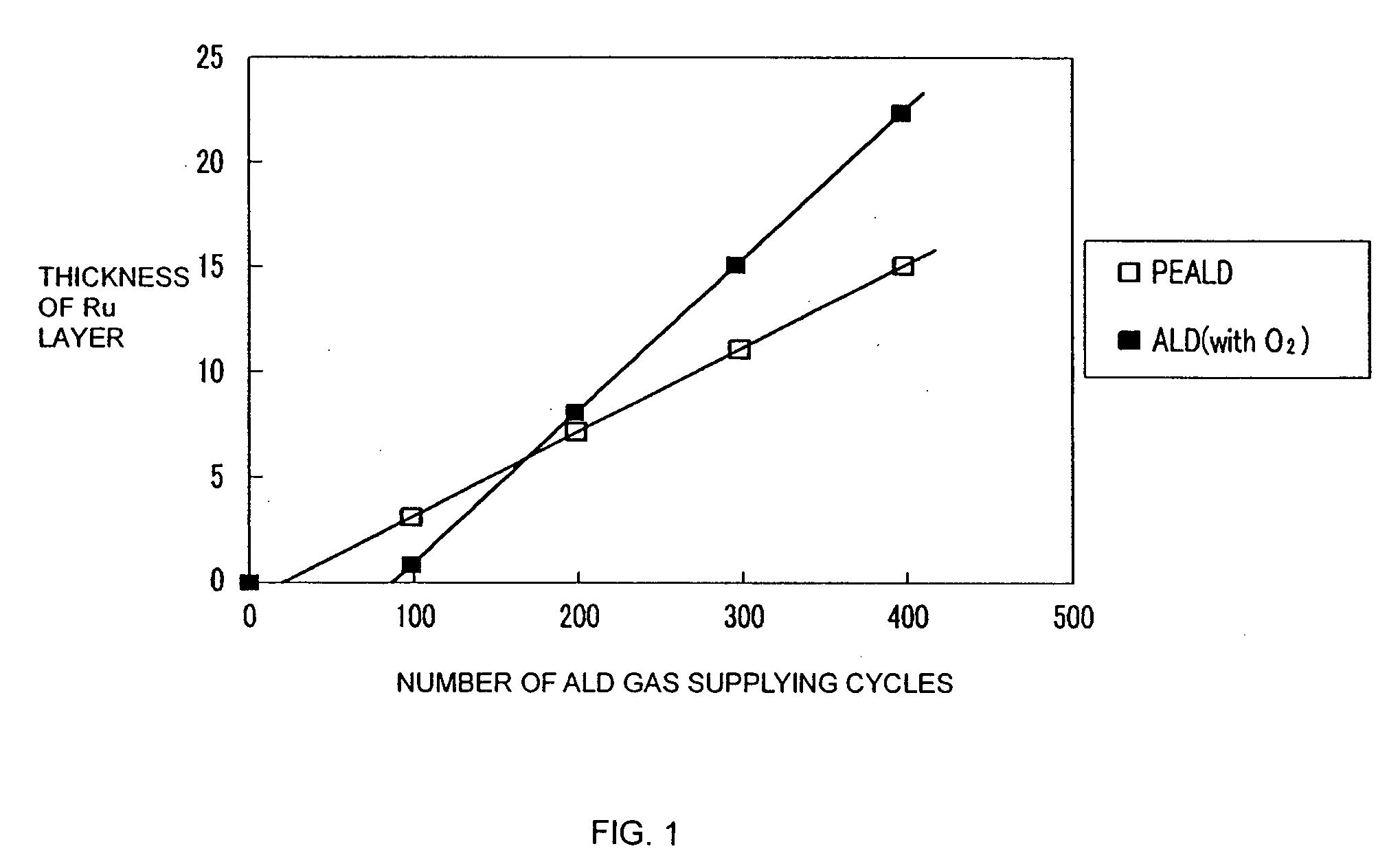
Because the incubation time is long and inconsistent, the thickness of the resulting ruthenium film may vary significantly after a fixed number of Ru thermal ALD gas supplying cycles.
In addition, the long incubation time can decrease the productivity of the Ru ALD apparatus.
Therefore, it takes longer to form a thick ruthenium film by the PEALD method than by the non-plasma ALD method.

Method used


Image

  • Method of depositing Ru films having high density
  • Method of depositing Ru films having high density
  • Method of depositing Ru films having high density

Examples


Embodiment Construction

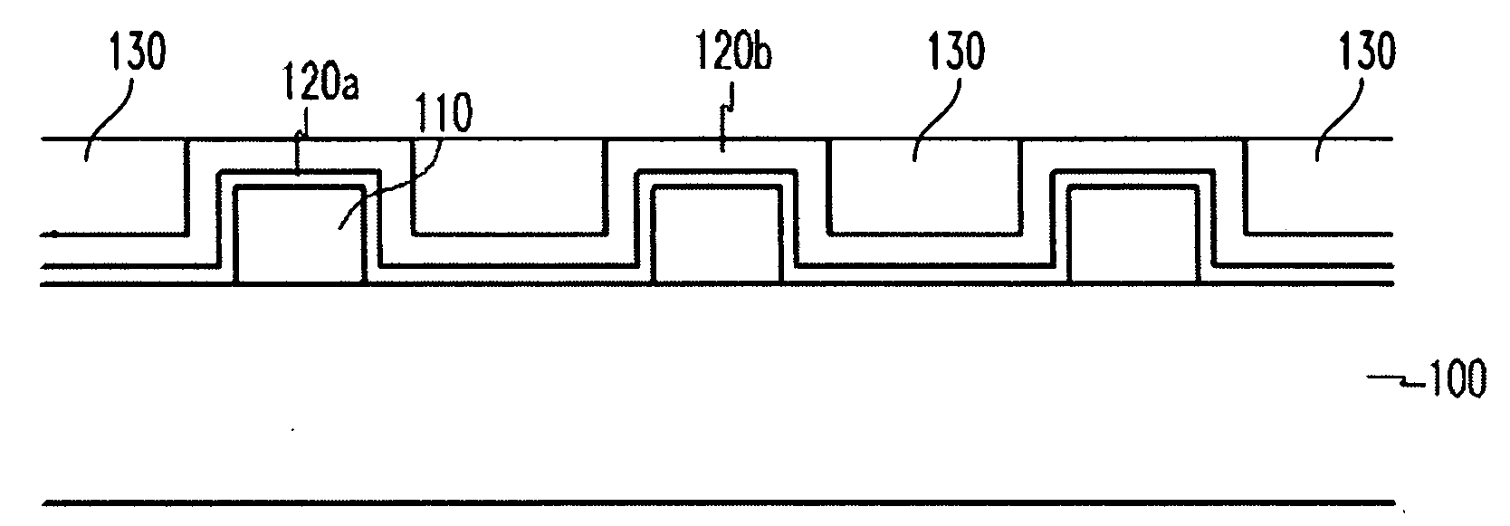
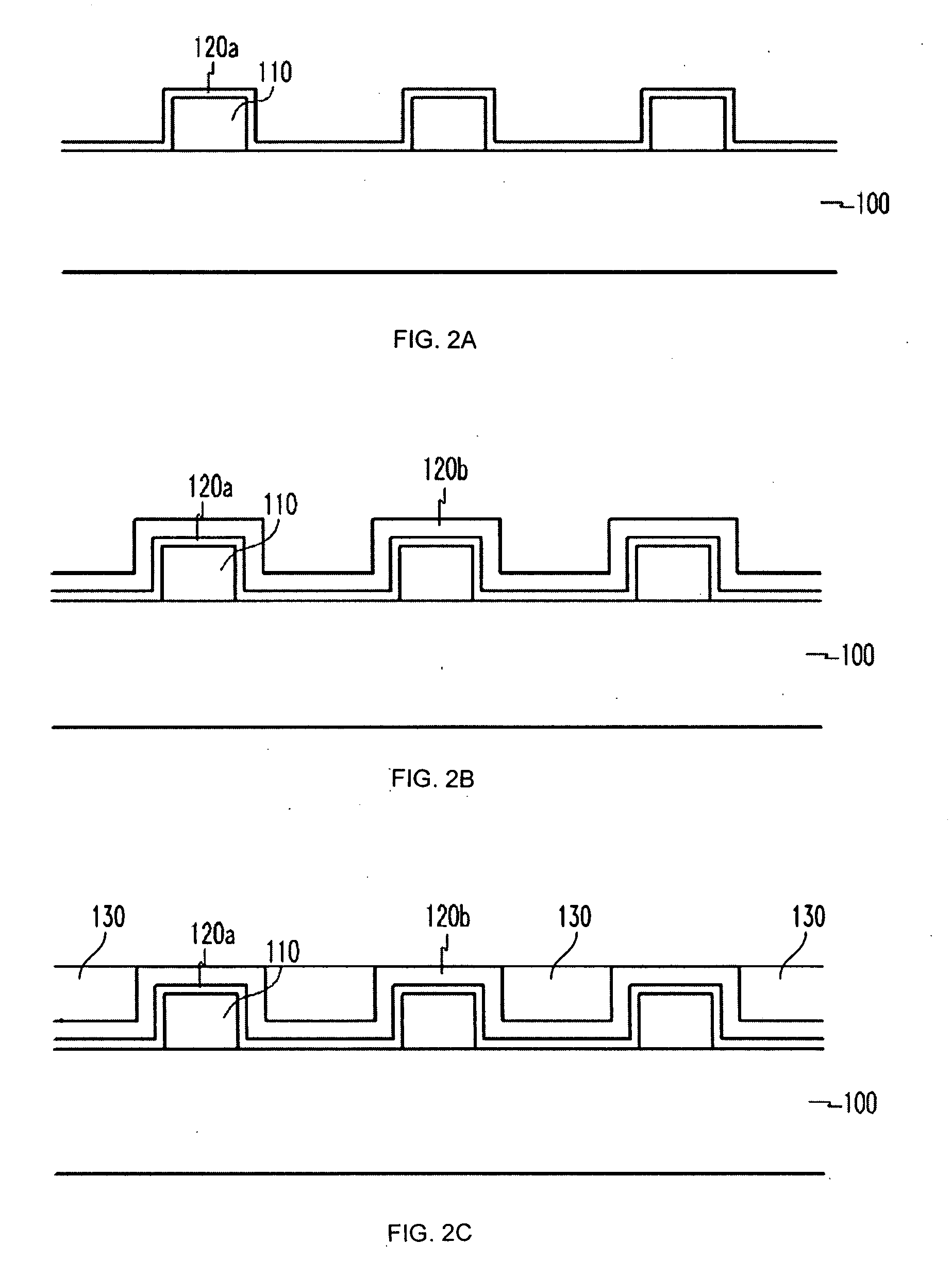
[0043]Hereinafter, exemplary embodiments will be described in detail with reference to the attached drawings. However, the invention is not limited to the embodiments but may be implemented in various forms.

[0044]In embodiments described below, while a gas supplying cycle of sequentially supplying a ruthenium source gas and a reaction gas is carried out for an ALD process, an inert gas such as argon (Ar) or nitrogen gas (N2) may be continuously supplied, including purge periods between ruthenium source and reaction gas pulses. Such inert gases may minimize or prevent the ruthenium gas and the reaction gas from being mixed with each other. Hydrogen gas (H2), nitrogen gas (N2), and a mixture thereof, which are reactive only in the plasma state thereof, may be used as a purging gas for purging the ruthenium source gas from a reactor. Instead of or in addition to the purging gas, a vacuum pump may be used to exhaust or remove the ruthenium source gas from the reactor. Detailed descripti...


PUM

PropertyMeasurementUnit
Temperatureaaaaaaaaaa

Abstract

A ruthenium film deposition method is disclosed. In one embodiment of the method, a first ruthenium film is deposited by using a PEALD process until a substrate is substantially entirely covered with the first ruthenium film. Then, a second ruthenium film is deposited on the first ruthenium film by using a thermal ALD process having a higher deposition speed than that of the PEALD process. In the method, a ruthenium metal film having a high density is formed in a short time by combining a PEALD process of depositing a ruthenium film at a low deposition speed and a deposition process of depositing a ruthenium film at a higher deposition speed. Accordingly, it is possible to form a ruthenium film having high density, a smooth surface, good adhesiveness, and a short incubation period. Therefore, according to the embodiment, in comparison to cases of using only a PEALD process or an ALD process that has a long incubation period, it is possible to obtain a ruthenium film having a large thickness and a high density in the same time interval. As a result, the ruthenium film formed by the ruthenium film deposition method according to the embodiment is more suitable for electrode structures of semiconductor devices than the ruthenium films formed by using conventional methods.

Description

PRIORITY CLAIM[0001]This application claims the priority benefit of Korean Patent Application No. 10-2006-0014807, filed on Feb. 15, 2006, the disclosure of which is incorporated herein by reference.BACKGROUND[0002]1. Field[0003]The present invention relates to a method of depositing a ruthenium (Ru) film, and more particularly, to a method of manufacturing semiconductor devices with Ru films having high density.[0004]2. Description of the Related Art[0005]Ruthenium films have been proposed to be used for thin film electrodes of semiconductor devices such as dynamic random access memories (DRAMs) and ferroelectric random access memories (FeRAMs). Ruthenium films to be used for the electrodes typically have a thickness of about 10 nm to about 20 nm.[0006]A ruthenium film can also serve as a barrier against diffusion of copper in semiconductor devices. In such a case, a ruthenium film can be in contact with a copper layer. In addition, a ruthenium film may serve to increase adhesion o...

Claims


Application Information

Patent Timeline
IPC IPC(8): H01L21/44H01L21/4763
CPCC23C16/18C23C16/45527H01L21/76846H01L21/28562C23C16/45536G07F17/32G06Q50/34A63F13/90A63F2250/146
Inventor PARK, HYUNG-SANG
Owner ASM KOREA LTD
Learn More