
Method of agitating solution

a technology of solution and stirring, which is applied in the field of stirring solution, can solve the problems of insufficient sensitivity of dna chips, inability to analyze such samples, and lower fluorescence intensity of genes, so as to achieve favorable use of the material for the container, prevent damage, and sufficient stirring of the analyte solution

Active Publication Date: 2007-08-02
TORAY IND INC
View PDF6 Cites 30 Cited by
  • Summary
  • Abstract
  • Description
  • Claims
  • Application Information

AI Technical Summary

Benefits of technology

[0070] When hybridization is performed in combination of a common flat plate-shaped DNA chip and a cover glass placed thereon, the distance between the cover glass and the DNA chip is approximately 10 μm at most. Use of fine particles larger in diameter results in clogging between the DNA chip and the cover glass, causing problems such as prohibition of movement of the fine particles and decrease in the advantageous effects of mixing fine particles. On the other hand, use of finer particles having a diameter of several μm, which is resistant to clogging between the cover glass and the DNA chip, for prevention of clogging and for movement of the fine particles by acceleration by gravity or vibration, only results in insufficient movement of the fine particles in the analyte solution, because the solution resistance becomes greater as the fine particles become smaller in size. Accordingly, there is still a problem that it is not possible to obtain favorable stirring effect with fine particles. Alternatively, expansion of the distance between the cover glass and the carrier for example with an O-ring and use of larger fine particles for sufficiently stirring cause the problem that the fluorescence intensity after hybridization deteriorates, presumably because the chip surface is damaged by the fine particles and the probe on the probe-immobilized surface is separated by collision of the fine particles.
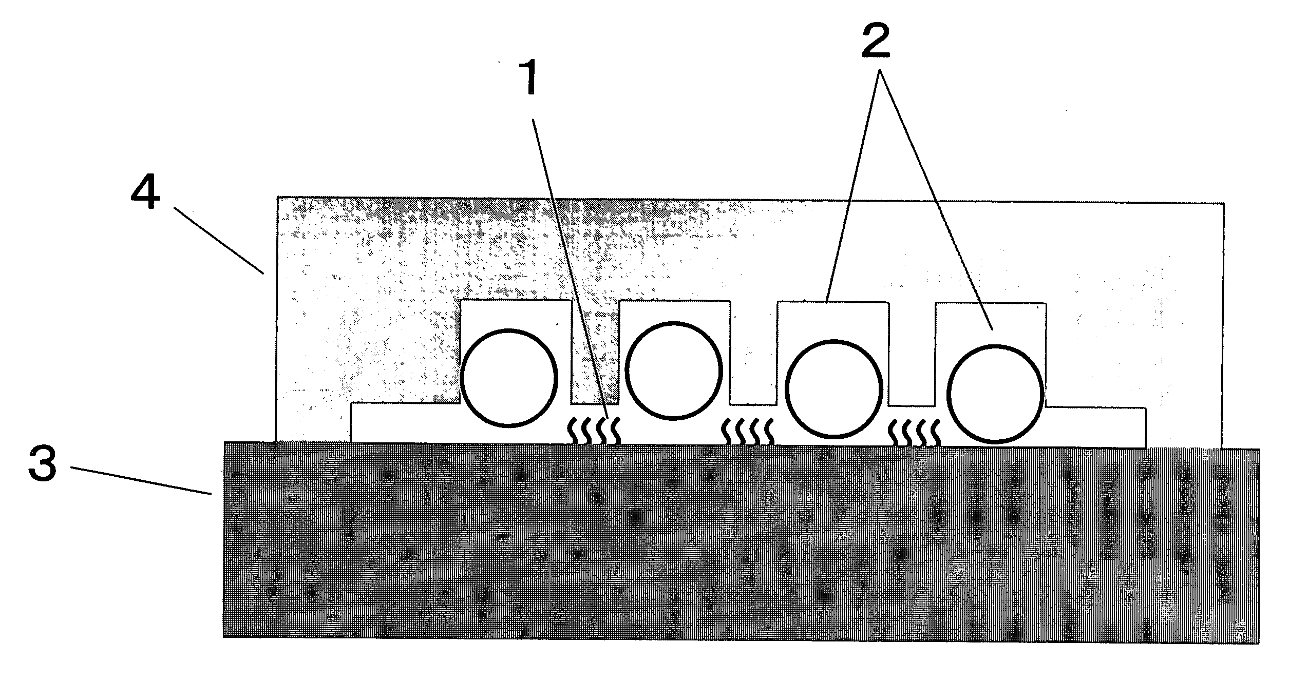
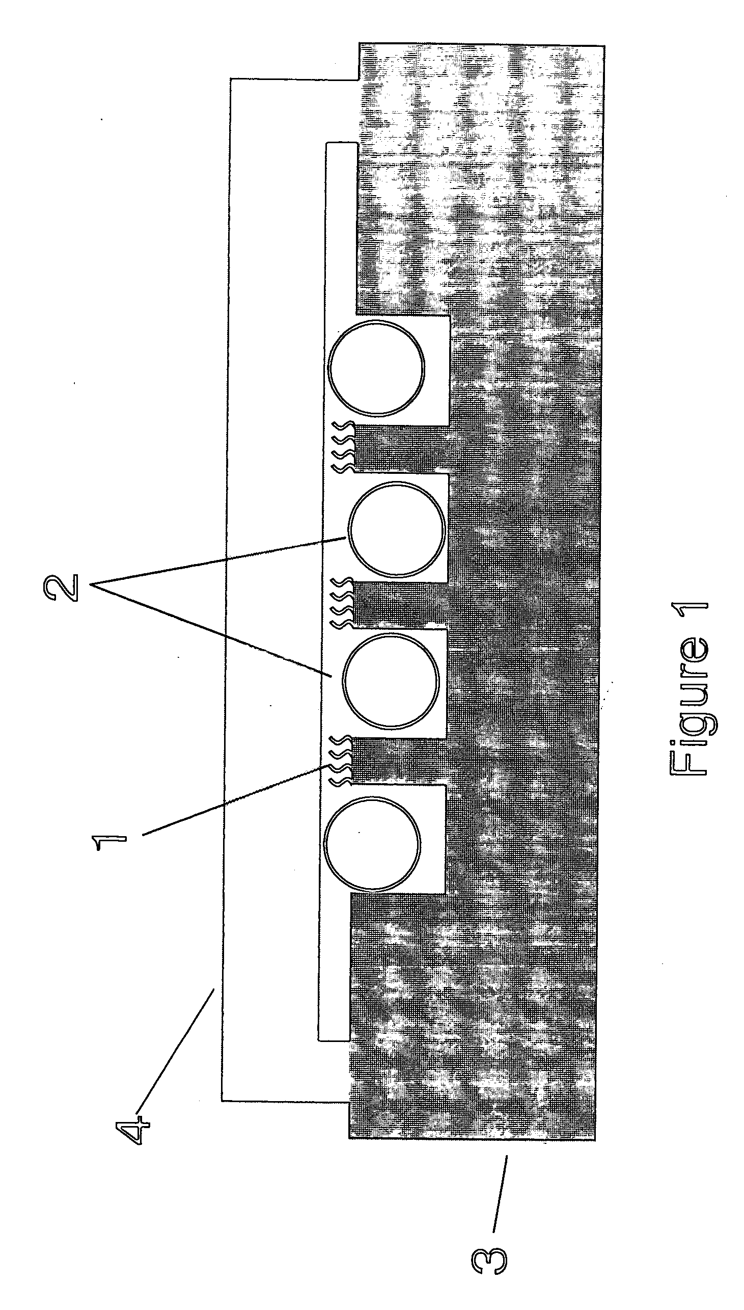
[0071] As in the favorable embodiments of the present invention, it is possible to increase the size of fine particles at least up to the height of the concave area and convex in the convex-concave area, as shown in FIGS. 1 and 2, by using a carrier having a convex-concave area or a container having a convex-concave area. Thus, it is possible to obtain advantageous effects allowing sufficient stirring of the analyte solution with larger fine particles and preventing damage on the probe DNA-immobilized face, by stirring a target DNA-containing analyte solution with fine particles while using a carrier having a convex-concave area or a container having a convex-concave area.
[0072] In the method of stirring solution according to the present invention, the material for the container favorably used is not particularly limited. Examples of the materials for the container favorably used in the present invention include glass, plastics, and the like. When the shape of the container is flat plate, a glass plate such as cover glass or slide glass is favorably used, and when the container has convex-concave shape, a plastic material such as polymethyl methacrylate or polycarbonate, which is injection moldable, is preferable from a point of productivity.
[0073] The material for the carrier for use in the present invention is not particularly limited. Favorable materials for the carrier include glass and various polymers (polystyrene, polymethyl methacrylate, and polycarbonate).
[0074] When the carrier material is glass, for immobilization of a selective binding substance, the carrier may be treated with a silane coupling agent for generation of functional groups on the surface and the selective binding substance such as DNA may be immobilized on the carrier by using the functional groups. It is possible to form amino groups on the surface of glass by using, for example, an aminoalkylsilane, and to immobilize, for example, DNA thereon by the electrostatic force between the plus charge of the amino group and the minus charge of DNA.
[0075] In the present invention, use of a solid material containing a polymer having a structural unit represented by the following General Formula (1) particularly as the carrier surface for immobilization of a selective binding substance is advantageous, because the signal after hybridization becomes greater.

Problems solved by technology

Current DNA chips are still insufficient in sensitivity, and thus, it would be impossible to analyze such a sample.
In addition, with a current DNA chip, the fluorescence intensity of genes lower in expression amount after hybridization is very low, and thus, the current DNA chips still have a problem that it is practically impossible to analyze such genes.
Accordingly, current DNA chips have a problem that how to increase the fluorescent intensity after hybridization of the samples lower in quantity and genes lower in expression amount.
For acceleration of the reaction between analyte DNA and probe, natural diffusion of the analyte is insufficient, and it is thought that accelerating the reaction between probe and analyte efficiently by stirring the solution.
However, the methods described in Published Japanese Patent Application Nos. 2003-248008 and 2003-339375 still had the following problems.
Thus, it caused a problem that fine particles larger in diameter than the clearance, when added, are held in the clearance between the DNA chip and the cover, prohibiting movement of the fine particles and making the stirring ineffective.
In addition, use of fine particles of several μm in diameter, caused a problem that the fine particles do not move in the analyte solution efficiently because of the solution resistance even if forced by gravity or the like, resulting in insufficient stirring.
However, the cover glass and the DNA chip are both flat in shape for sealing, and thus, the fine particles move through the DNA probe-immobilized region.
As a result, the fine particles often damaged the probe DNA-immobilized region, causing problems such as difficulty of data analysis and decrease in signal intensity because of separation of the probe by collision of the fine particles to the probe-immobilized surface.

Method used


Image

  • Method of agitating solution
  • Method of agitating solution
  • Method of agitating solution

Examples


example 1

[0113] (Preparation of DNA-Immobilized Support)

[0114] A mold for injection molding was prepared according to a known LIGA (Lithographie Galvanoformung Abformung) process, and a PMMA substrate having the shape described below was prepared by injection molding. The PMMA used in this Example had an average molecular weight of 50,000 and contained carbon black (#3050B, manufactured by Mitsubishi Chemical Corp.) at a ratio of 1 wt %, and the substrate was black in appearance. When the spectroscopic reflectance and transmissibility of the black substrate were determined, the spectroscopic reflectance was 5% or less at a wavelength in the visible light range (wavelength: 400 to 800 nm), and the transmissibility was 0.5% or less at a wavelength in the same range. The substrate had a uniformly flat spectrum without a particular spectral pattern (e.g., peaks) both in spectroscopic reflectance and transmissibility in the visible light range. The spectroscopic reflectance is a spectroscopic re...

example 2

[0141] An experiment on stirring efficiency was performed by using air bubbles. The experiment procedure was similar to that in Example 1, except that 0.9 μL of air bubble was injected with a microsyringe, instead of adding glass beads, when a cover glass is placed in the hybridization step. The carrier was fixed in such a direction that the revolving plate of rotator tilted into the vertical direction and the probe-immobilized face of the carrier became in parallel, and rotated, allowing air bubbles to migrate only around the sealed analyte solution. In this way, air bubbles were kept separated from the probe-immobilized face. Results are summarized in Table 1. Advantageous effects similar to those in Examples were observed.

example 3

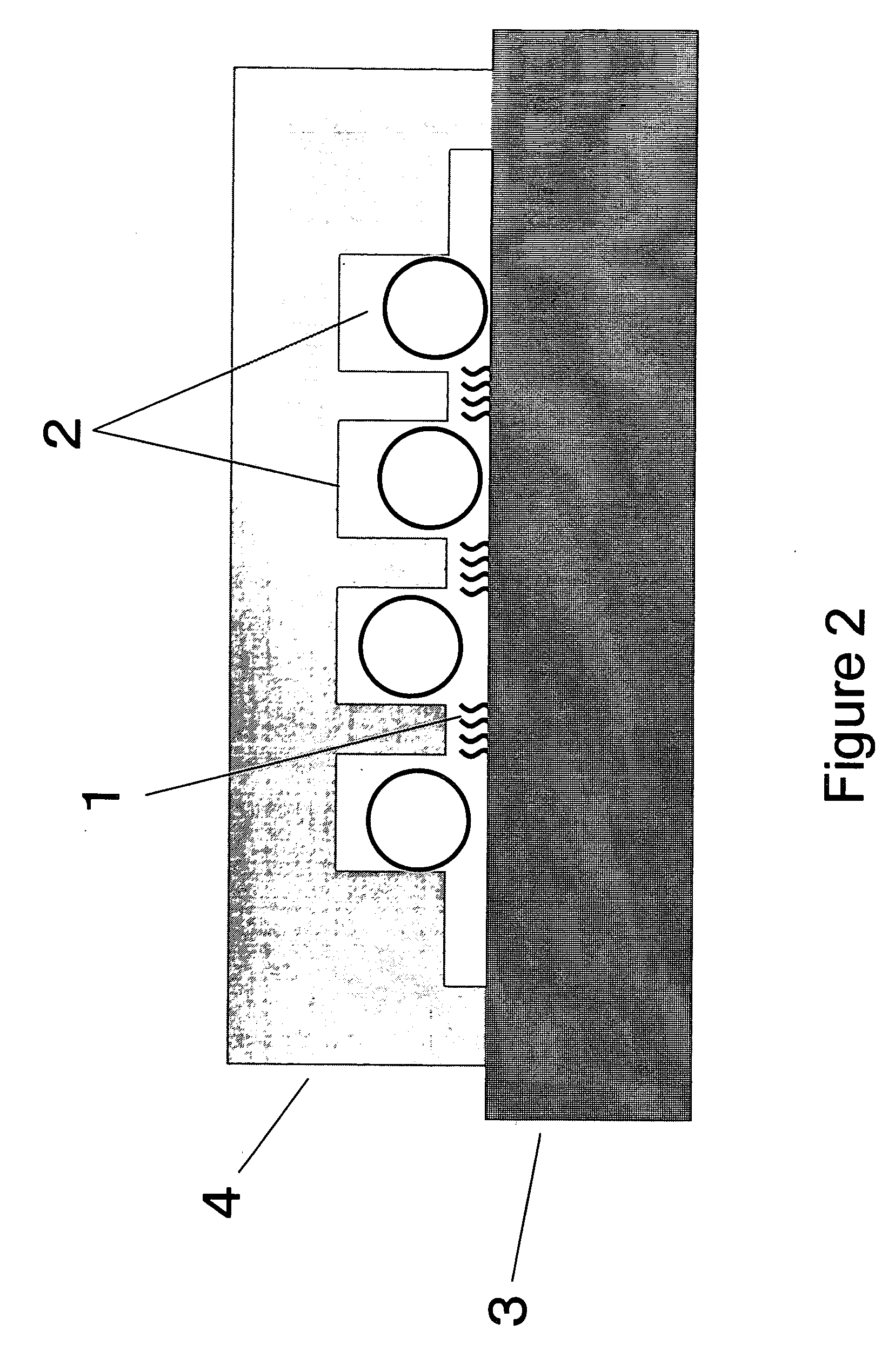
[0142] An experiment similar to Comparative Example 2 was performed, by using a container for solution 4 having the cross-sectional structure shown in FIG. 2 instead of a glass cover. That is, the convex-concave structure was formed not on the carrier but on the cover. The container and the flat PMMA carrier were placed carefully in the spatial relationship shown in FIG. 2. In subsequent hybridization while the beads are agitated, it was possible to move the glass beads without contact thereof with the probe DNA-immobilized face 1, because the distance between the probe DNA-immobilized face and the container for solution 4 was smaller than the diameter of the glass beads 2. Results are summarized in Table 1. The fluorescence intensity obtained was similar to that in Example 1. Considering the results in Comparative Example 2 as well, it seems important that the beads do not become in contact with the probe-immobilized face. In the method of the present Example, accurate positioning ...


PUM

PropertyMeasurementUnit
Widthaaaaaaaaaa
Heightaaaaaaaaaa
Widthaaaaaaaaaa

Abstract

The method of stirring a solution according to the present invention is a method of stirring a solution comprising contacting a selective binding substance immobilized on the surface of a carrier with a solution containing an analyte substance reactive with the selective binding substance, and mixing the fine particles or air bubbles into the solution containing an analyte substance, and moving the fine particles or air bubbles without allowing contact thereof with the selective binding substance-immobilized surface. The present invention provides a stirring method that accelerates the reaction of a carrier-immobilized selective binding substance with an analyte substance and detects a trace amount of analyte at high signal intensity and high S / N ratio. The present invention enables diagnosis and examination in the clinical setting by using a selective binding substance-immobilized carrier such as DNA chip.

Description

TECHNICAL FIELD [0001] The present invention relates to a method of stirring a solution containing an analyte substance, when a carrier-immobilized selective binding substance is allowed to react with an analyte substance by bringing a carrier carrying an immobilized substance selectively binding to an analyte substance (“selective binding substance” in the present description) into contact with a solution containing an analyte substance. More specifically, it relates to a method of stirring a solution containing an analyte substance for acceleration of the reaction between a carrier-immobilized selective binding substance and the analyte substance. BACKGROUND ART [0002] Research for analysis of genetic information of various organisms is now under progress. A great number of genes including those of human, the base sequences thereof, proteins coded by the gene sequences, and sugar chains produced secondary from these proteins are now being elucidated quite rapidly. The functions of...

Claims


Application Information

Patent Timeline
IPC IPC(8): G01N1/00B01F33/40C12M1/02C12N15/09C12Q1/68G01N1/36G01N33/53G01N35/00G01N35/02G01N37/00
CPCB01F13/0052B01F13/0054B01F13/0059Y10T436/25G01N2035/00158G01N2035/00544B01F13/02B01F33/251B01F33/252B01F33/40B01F33/30C12N11/00
Inventor TAKII, YUKINAGINO, KUNIHISANAKAMURA, FUMIONOBUMASA, HITOSHI
Owner TORAY IND INC
Learn More