Component package having heat exchanger
a technology of components and heat exchangers, applied in the direction of cooling/ventilation/heating modifications, semiconductor/solid-state device details, semiconductor devices, etc., can solve the problems of increasing the thickness of the package, the inability to mount the electrical equipment, and the inability to adequately cool the semiconductor integrated circuit b>205/b>, etc., to achieve excellent heat-radiating functionality.
- Summary
- Abstract
- Description
- Claims
- Application Information
AI Technical Summary
Benefits of technology
Problems solved by technology
Method used
Image
Examples
embodiment a
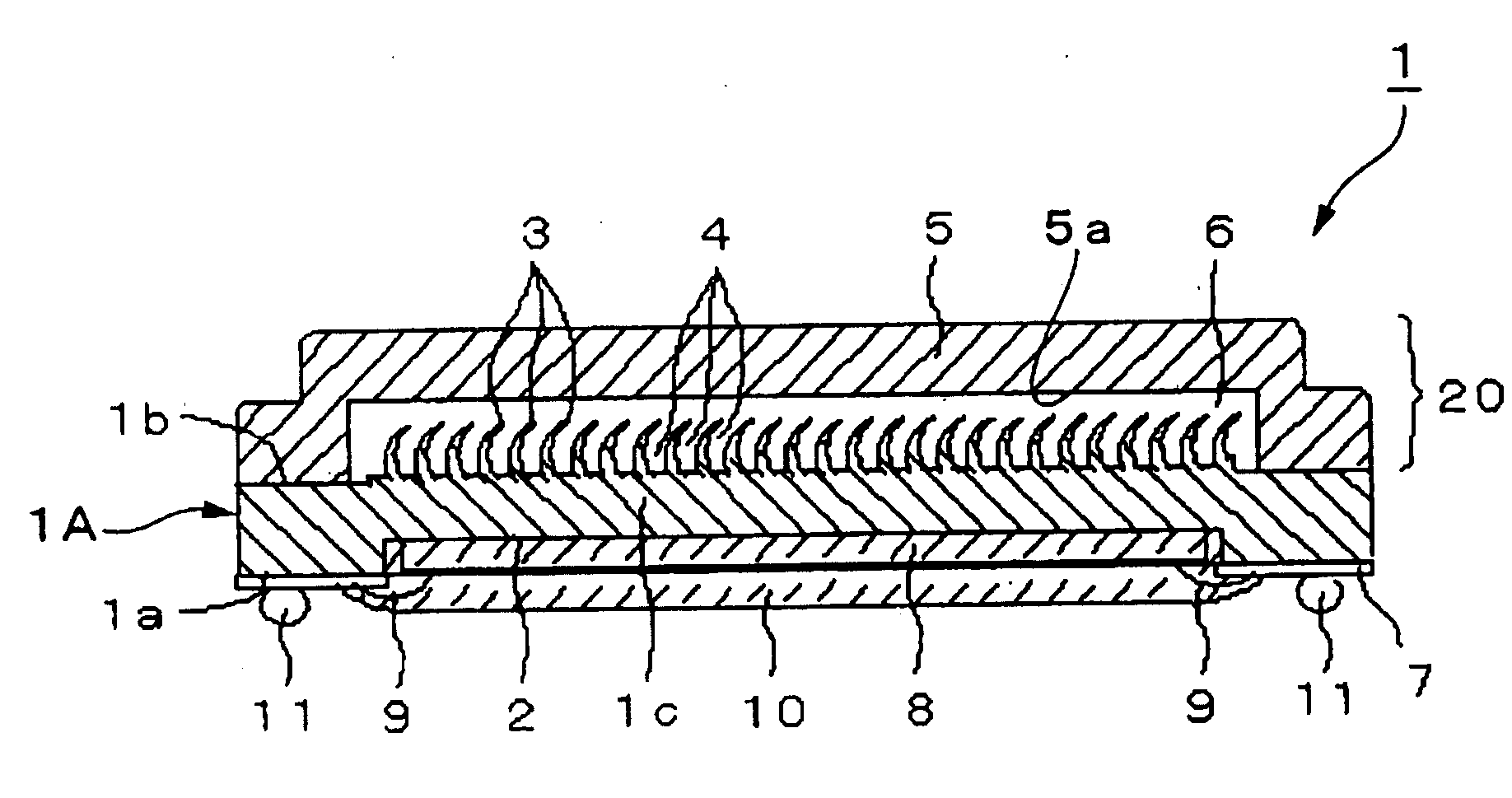
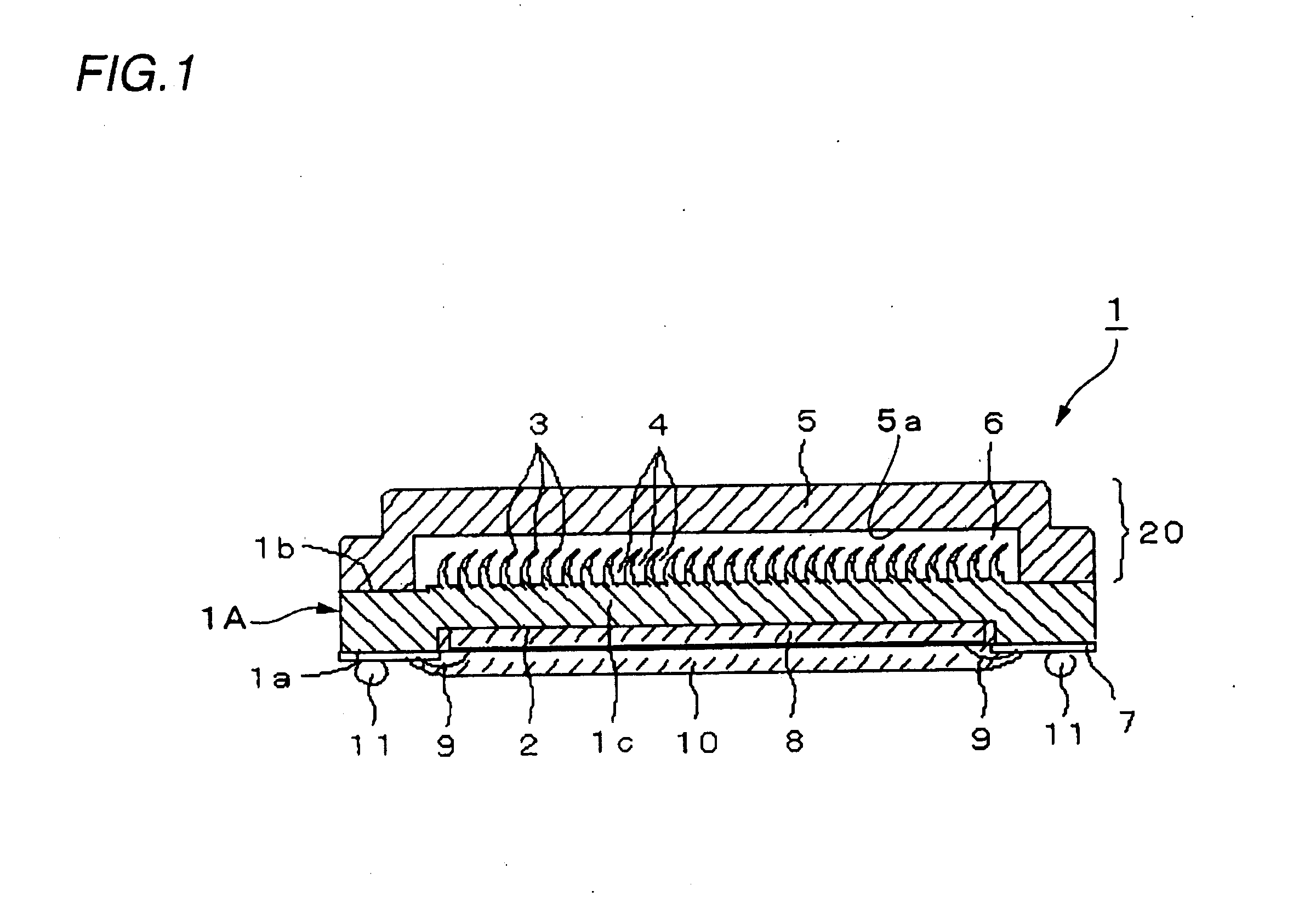
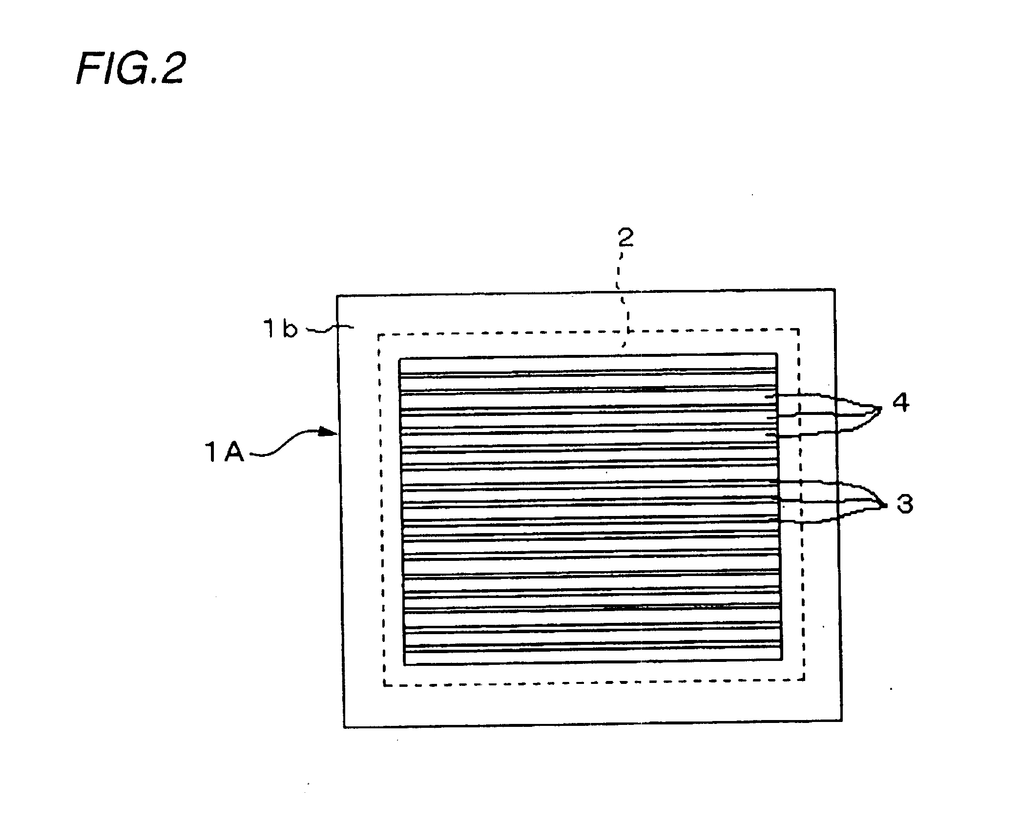
[0065]FIG. 1 is a cross-sectional view that shows an electrical component package having a liquid-cooled heat exchanger according to embodiment A. FIG. 2 is a plan view that shows the liquid-cooled heat exchanger of embodiment A. FIG. 3 is a perspective view that shows a partial cross section of embodiment A.
[0066] A main-body plate 1A (first plate member) of an electrical component package 1 having a liquid-cooled heat exchanger (abbreviated below as “package 1”) is formed from a metal plate. The metal plate has rigidity, good thermal conductivity, a thermal expansion coefficient that is compatible with the thermal expansion coefficients of the wiring substrate and the like described hereinafter, and is capable of being subjected to deformation processing. Stainless steel, aluminum, or a copper alloy can be used as the metal plate.
[0067] The main-body plate 1A of the package has a square concavity 2 (component-mounting concavity) formed on a surface 1a. The entirety of the main-b...
modified example 1 of embodiment a
[0106]FIGS. 11A through 11C are descriptive diagrams that show a modified example of embodiment A. A package 1B of the present example is even thinner than the aforedescribed package 1. As shown in FIG. 11A, the concavity 2, which has a prescribed depth, is formed by pressing a punch that is affixed to a press (not shown) onto the surface 12a on one side of the flat metal plate 12 to form the main-body plate 1A of the package. The convexity 15 that protrudes from the opposite surface 12b of the metal plate 12 at a height that is substantially equal to the depth of the concavity 2 is formed due to the formation of the concavity 2. The convexity 15 is then divided once or a plurality of times by, e.g., a cutter 55 and removed, becoming the same height as the rest of the surface around the convexity-forming portion.
[0107] Next, as shown in FIG. 11B, the fins 3 are formed by carving out the flattened surface 12b using the carving tool 30, and the numerous channels 4 of the liquid-coole...
modified example 2 of embodiment a
[0112]FIGS. 12 and 13 are descriptive diagrams that show an example that is even thinner than the package 1. As shown in FIG. 12, a package 60 of the present example has channels that are shallower than in the previously described package 1B. Specifically, the tops of fins 61 are cut off, whereby flat surfaces 61a are formed, the cross sections of the channels 62 are made into a substantially square shape, and the depth of the channels 62 is reduced.
[0113] The method for forming the channels 62 is similar to the method of formation that was described with reference to FIGS. 11A and 11B. First, once the metal plate 12 has been mounted and secured in place in a die 70, the steps for carving the surface on one side of the metal plate 12 are carried out repeatedly using the carving tool 30, whereby the numerous fins 61 are formed having a prescribed height and the channels 62 are formed between the fins 61, as shown in FIG. 13A.
[0114] The tops of the fins 61 formed on the surface on o...
PUM
 Abstract
Description
Claims
Application Information
 - R&D
- Intellectual Property
- Life Sciences
- Materials
- Tech Scout
- Unparalleled Data Quality
- Higher Quality Content
- 60% Fewer Hallucinations
Browse by: Latest US Patents, China's latest patents, Technical Efficacy Thesaurus, Application Domain, Technology Topic, Popular Technical Reports.
© 2025 PatSnap. All rights reserved.Legal|Privacy policy|Modern Slavery Act Transparency Statement|Sitemap|About US| Contact US: help@patsnap.com


