Eureka AIR delivers breakthrough ideas for toughest innovation challenges, trusted by R&D personnel around the world.

Gas separation membranes and processes for controlled environmental management

a technology of environmental management and gas separation membrane, applied in the direction of membranes, separation processes, dispersed particle separation, etc., can solve the problems of affecting the water flux across the membrane, high permeability, and often not being able to meet the requirements of a controlled environment, so as to reduce the resistance to permeation and improve the effect of water flux

Inactive Publication Date: 2007-07-05
MEMBRANE TECH & RES
View PDF16 Cites 29 Cited by
  • Summary
  • Abstract
  • Description
  • Claims
  • Application Information

AI Technical Summary

Benefits of technology

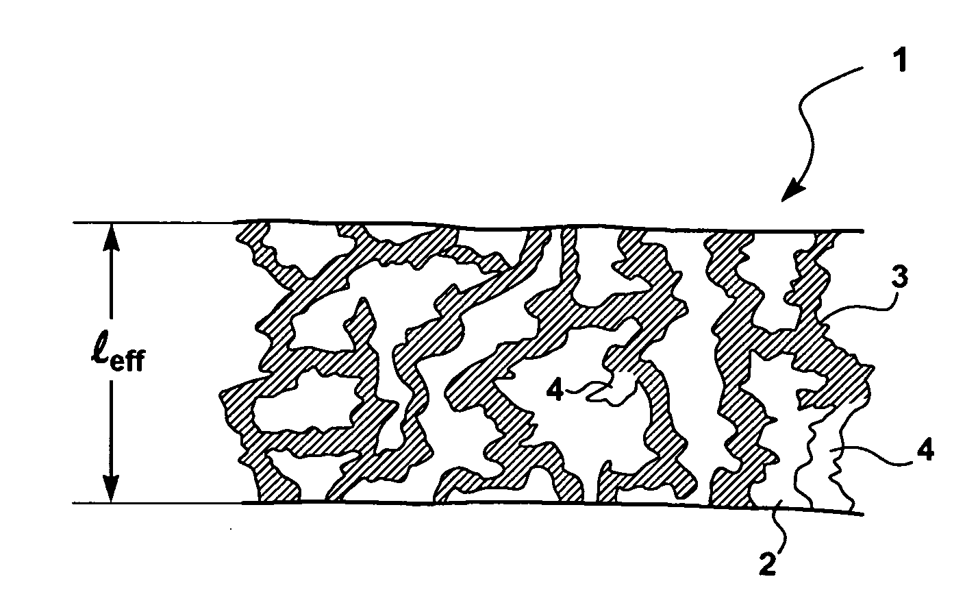
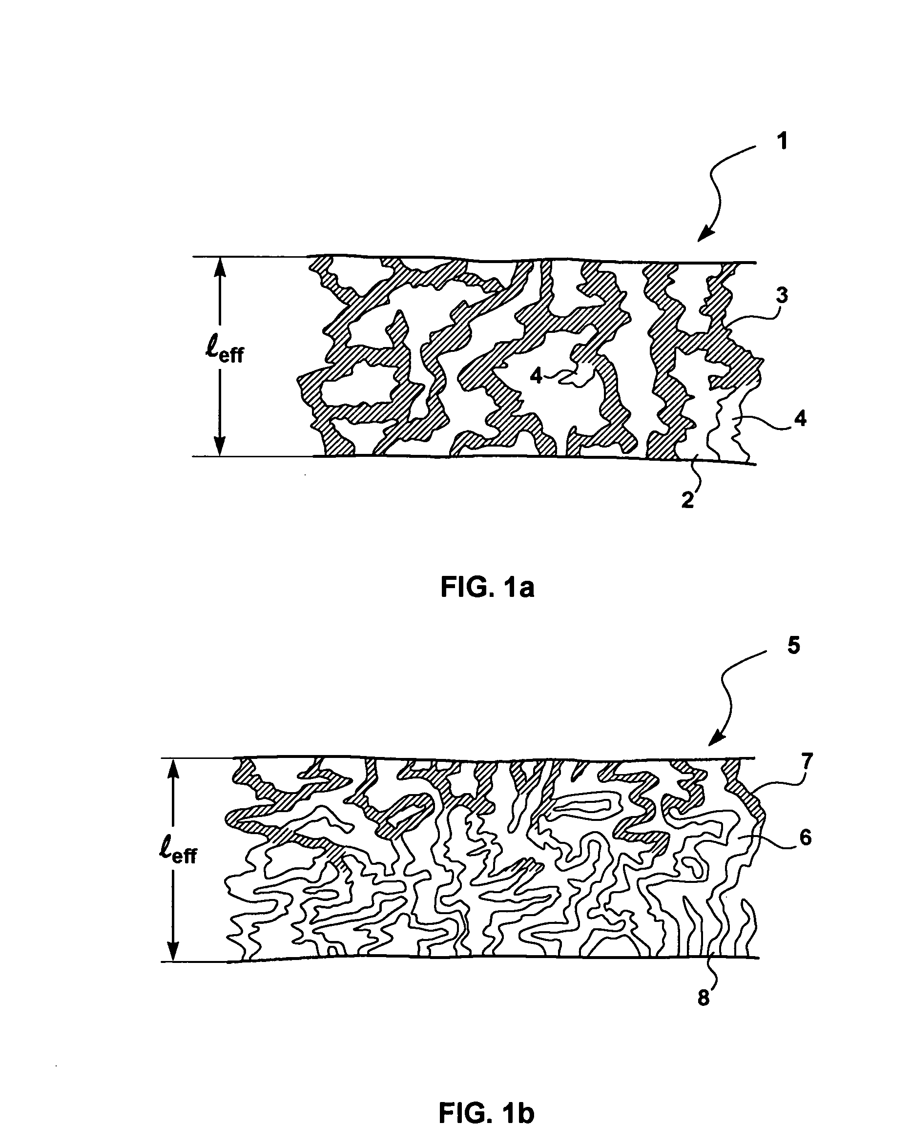
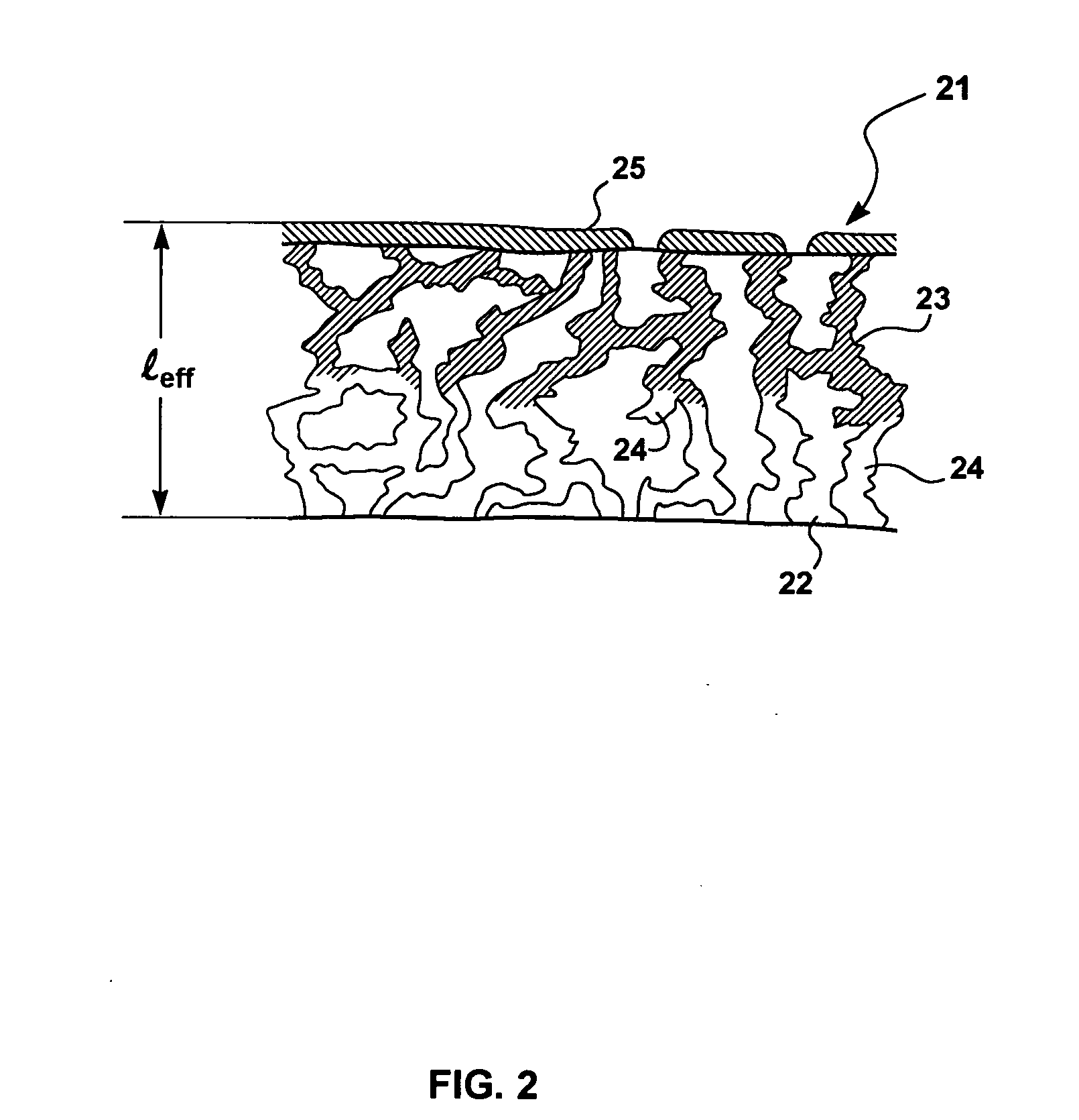
The invention is a membrane, membrane module, and membrane process for controlling humidity in an environment by creating a gas stream with a desired water-vapor content and passing it into the environment. The membrane used in the process has a high permeability to water vapor, but faces resistance when trying to pass water vapor through it. This resistance is caused by the design of the membrane, which has layers that allow for stagnant gas inside. The invention solves this problem by reducing the resistance to water vapor transport inside the membrane.

Problems solved by technology

Unfortunately, when such a polymer is used to make a water-selective membrane, however, this extremely high permeability often does not translate to correspondingly extremely high water flux across the membrane.

Method used


Image

  • Gas separation membranes and processes for controlled environmental management
  • Gas separation membranes and processes for controlled environmental management
  • Gas separation membranes and processes for controlled environmental management

Examples


example 1

Preparation of Microporous Support Layer for Composite Membranes—not in Accordance with the Invention

[0175]A series of microporous support membranes was made according to standard casting techniques used to prepare composite gas-separation membranes. A casting solution of polyetherimide (PEI) in a water-miscible solvent was prepared and doctored onto a moving backing web of polyester. The web was passed into a water bath, where the polymer precipitated to form the film. The coated web was collected on a take-up roll, washed to remove any remaining solvent, and dried to form the support film.

[0176]The result was a series of two-layer structures, of total thickness in the range 120-150 μm. The microporous support layer had an asymmetric structure, graded to a very fine, almost dense skin layer.

example 2

Preparation of a Typical Composite Gas Separation Membrane—not in Accordance with the Invention

[0177]A polydimethylsiloxane (PDMS) sealing / gutter layer was dip-coated onto a microporous support prepared as in Example 1. The PDMS layer was dip-coated with single pass through a solution of 2.5 wt % Pebax® 2533 (Atochem Inc., Glen Rock, N.J.) in ethanol, which formed the selective layer. The resulting membrane had four discrete layers: a backing layer, a microporous support layer, a gutter layer and a selective layer. The membrane was 150 μm thick overall and was designated as Sample 1.

example 3

Preparation of a Three-Layer Composite Membrane—not in Accordance with the Invention

[0178]A microporous support of the type described in Example 1 was single-coated with a solution of 0.5 wt % Pebax® 1657 in butanol to form a selective layer. This membrane differed from Sample 1 in that no gutter layer was included and a more hydrophilic grade of Pebax was used. The resulting membrane was 125 μm thick and was designated as Sample 2.


PUM

PropertyMeasurementUnit
RHaaaaaaaaaa
vol %aaaaaaaaaa
thicknessaaaaaaaaaa

Abstract

A gas-separation membrane, membrane module and membrane process for controlling humidity in an environment. The membrane has a porous support zone impregnated by a selective zone, a configuration that reduces concentration polarization within the membrane itself when the membrane is housed in the module and used in the process.

Description

[0001]This application claims the benefit of U.S. Provisional Application Ser. No. 60 / 755,380, filed Dec. 30, 2005 and incorporated herein by reference.FIELD OF THE INVENTION[0002]The invention relates to gas separation membranes, and specifically to the use of gas separation membranes to maintain a controlled environment.BACKGROUND OF THE INVENTION[0003]Gas separation membranes have been in industrial use for close to 25 years. Various types of membrane are available, although almost all commercially successful membranes are polymeric membranes formed as flat sheets or hollow fibers. Such polymeric membranes typically have a composite structure, comprising a relatively unselective microporous support membrane, which provides mechanical strength, coated with at least one thin selective layer of another material, which is primarily responsible for the separation properties.[0004]The membrane may take the form of an integral asymmetric membrane, in which the support and the selective ...

Claims


Application Information

Patent Timeline
Patent Type & Authority Applications(United States)
IPC IPC(8): B01D53/22
CPCB01D53/228B01D63/10B01D63/12B01D67/0009B01D2325/28B01D71/56B01D71/80B01D2257/80B01D2325/20B01D71/52
Inventor MERKEL, TIMOTHY CHARLES
Owner MEMBRANE TECH & RES
Why Eureka
Eureka Blog
Learn More