Apparatus and method for transport of microscopic object(s)

Inactive Publication Date: 2007-06-28
SEC
View PDF6 Cites 14 Cited by
  • Summary
  • Abstract
  • Description
  • Claims
  • Application Information

AI Technical Summary

Benefits of technology

[0010] Yet further object of the present invention is to provide for a system and method for controlled optical transportation of microscopic objects in transverse plane wherein the sense, speed as well as the direction of transport can be fully controlled.
[0084] Importantly, since the asymmetric gradient force and thus the acceleration or velocity of projection depends on the optical and geometric properties of particles, sorting of different particles based on difference in these properties is possible.

Problems solved by technology

However the use of photo-kinetic impulse from a pulsed laser beam to transport the microscopic objects can neither be used for intra-cellular transport nor transport in transverse plane (plane perpendicular to laser beam propagation).
However, in this method of transportation, axial light scattering force can lead to transportation only in the direction of light generating the scattering force and transportation in directions other than this require use of additional beams and fabrication of special chambers and is therefore not generally applicable.
Further such method cannot be used for intra-cellular transport and transport in transverse plane (plane perpendicular to laser beam propagation).
Such method of laser guided transport of particles inside hollow optical fiber cannot be used for intra-cellular transport and is also limited by maneuverability of the guiding optical fiber.
While this method is most obvious method of optical transport the same has also certain limitations in terms of speed and the number of particle that can be transported simultaneously.
However, the method and system disclosed herein can only be used for transportation of a trapped object in the said manner and therefore suffers with the same limitations as for U.S. Pat. No. 5,212,382.
Further, it cannot be used for channeling, accelerating and sorting of microscopic objects.

Method used


Image

  • Apparatus and method for transport of microscopic object(s)
  • Apparatus and method for transport of microscopic object(s)
  • Apparatus and method for transport of microscopic object(s)

Examples


Embodiment Construction

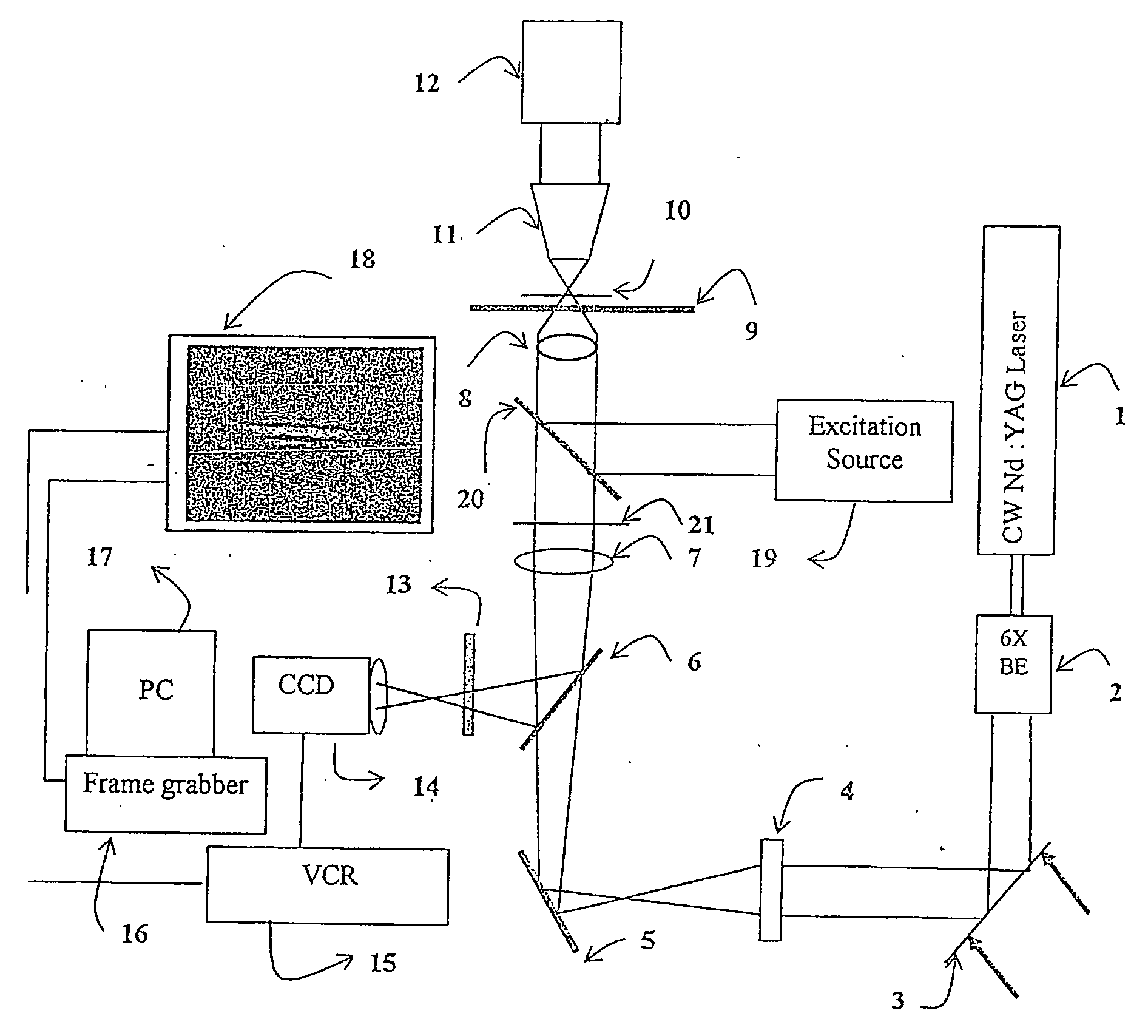
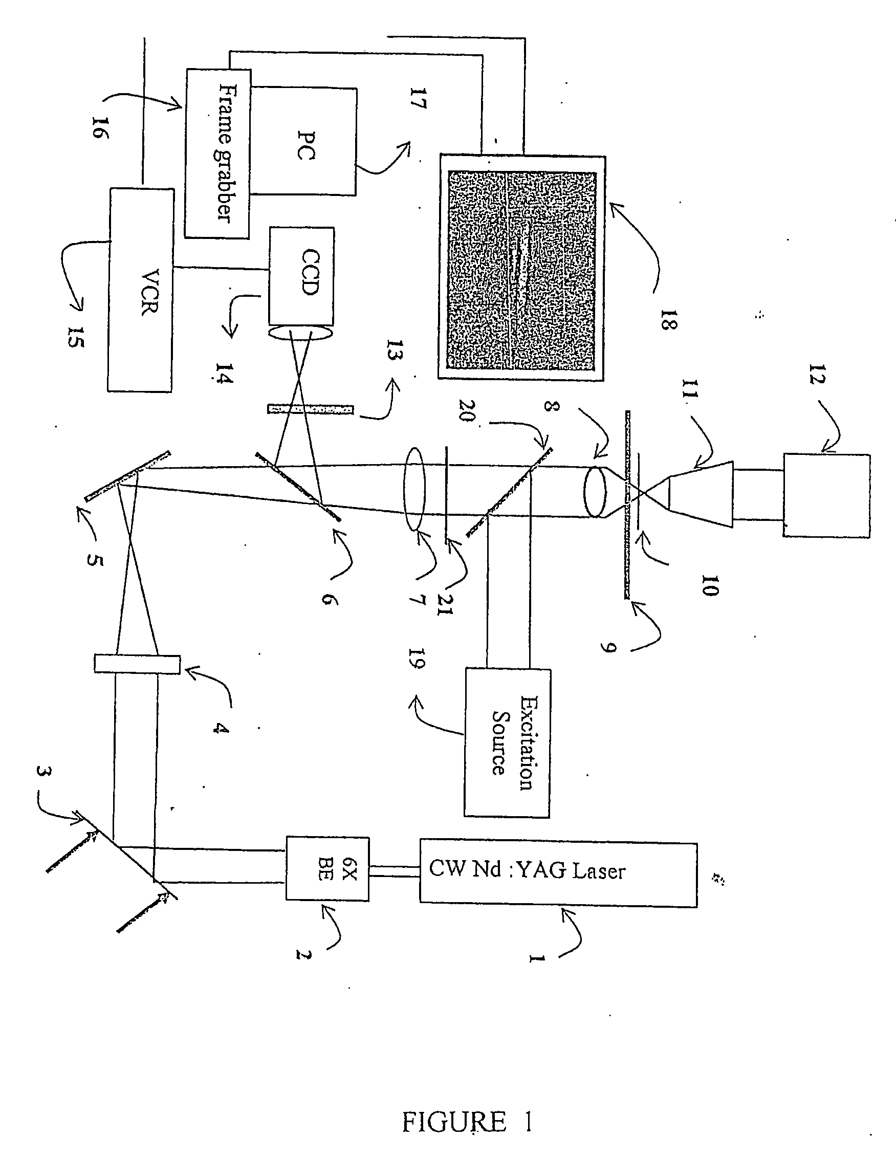
[0096] As shown in said FIG. 1, a zero order Hermite-Gaussian (TEM00) mode output of 1064 nm cw Nd: YAG laser (1) is expanded using a beam expander (2), steered through beam-steering device (3) and coupled to a 100× microscope objective (8) through a combination of cylindrical (4) and spherical lenses (7). The laser beam is focused to an elliptical spot in the specimen plane of the microscope. The beam expander (2) is a combination of two convex lenses of focal lengths 25 mm and 150 mm, placed at a distance of 175 mm to expand and collimate the beam from 1.5 mm to 9 mm. The beam-steering device (3) consists of three mirrors required to steer as well as align the beam with respect to the cylindrical lens (4) and the microscope objective (8). The cylindrical lens (4) has focal length of about 200 mm and is placed externally to the microscope at a distance of about 400 mm from the about 200 mm focal length tube lens (7) present inside the microscope. The laser beam was coupled to the m...


PUM


Abstract

A system and the method for transport of microscopic objects / particles involving the use of laser source operatively connected to a microscope objective which is adapted to generate optical focal spots on said particle(s) with asymmetric intensity profile in transverse plane followed by varying the said asymmetry of the gradient optical forces on the micron sized object / particles to thereby transport the microscopic object(s). The system and the method can be used to transport microscopic objects including i) transportation of cells and intra-cellular organelles, ii) acceleration of microscopic objects along any direction in a plane transverse to the direction of propagation of laser beam, iii) optical channeling of objects through a micro-capillary from one micro-well to another and transfer to another channel after desired processing, iv) sorting of microscopic objects, v) optical control of micro-machines, micro-fluidic devices etc. Importantly the apparatus and the method of the invention would have use in various biotechnological and micro electromechanical systems. Also the system and method for optical transportation of microscopic objects, would be capable of transporting objects of varying dimensions ranging from sub-micron to few tens of microns.

Description

FIELD OF THE INVENTION [0001] The present invention relates to an apparatus and a method for transport of microscopic objects. In particular, the apparatus and the method of the invention are directed to the transport of microscopic objects including i) transportation of cells and intra-cellular organelles, ii) acceleration of microscopic objects along any direction in a plane transverse to the direction of propagation of laser beam, iii) optical channeling of objects through a micro-capillary from one micro-well to another and transfer to another channel after desired processing, iv) sorting of microscopic objects, v) optical control of micro-machines, micro-fluidic devices etc. Importantly the apparatus and the method of the invention would have use in various biotechnological and micro electromechanical systems. BACKGROUND ART [0002] Various systems and methods for transportation of microscopic objects for various applications are presently in use. [0003] U.S. Pat. No. 5,998,129 ...

Claims


Application Information

Patent Timeline
IPC IPC(8): G01N21/00G21K1/00
CPCG21K1/006
Inventor MOHANTY, SAMARENDRA KUMARGUPTA, PRADEEP KUMAR
Owner SEC
Why Eureka
Try Eureka