
Regeneration of ionic liquid catalyst by hydrogenation using metal and acid

a technology hydrogenation, which is applied in the field of regeneration of catalysts, can solve the problems of deactivation of ionic liquid catalyst, loss of activity, and need to be replaced

Active Publication Date: 2007-06-21
CHEVROU USA INC
View PDF9 Cites 75 Cited by
  • Summary
  • Abstract
  • Description
  • Claims
  • Application Information

AI Technical Summary

Benefits of technology

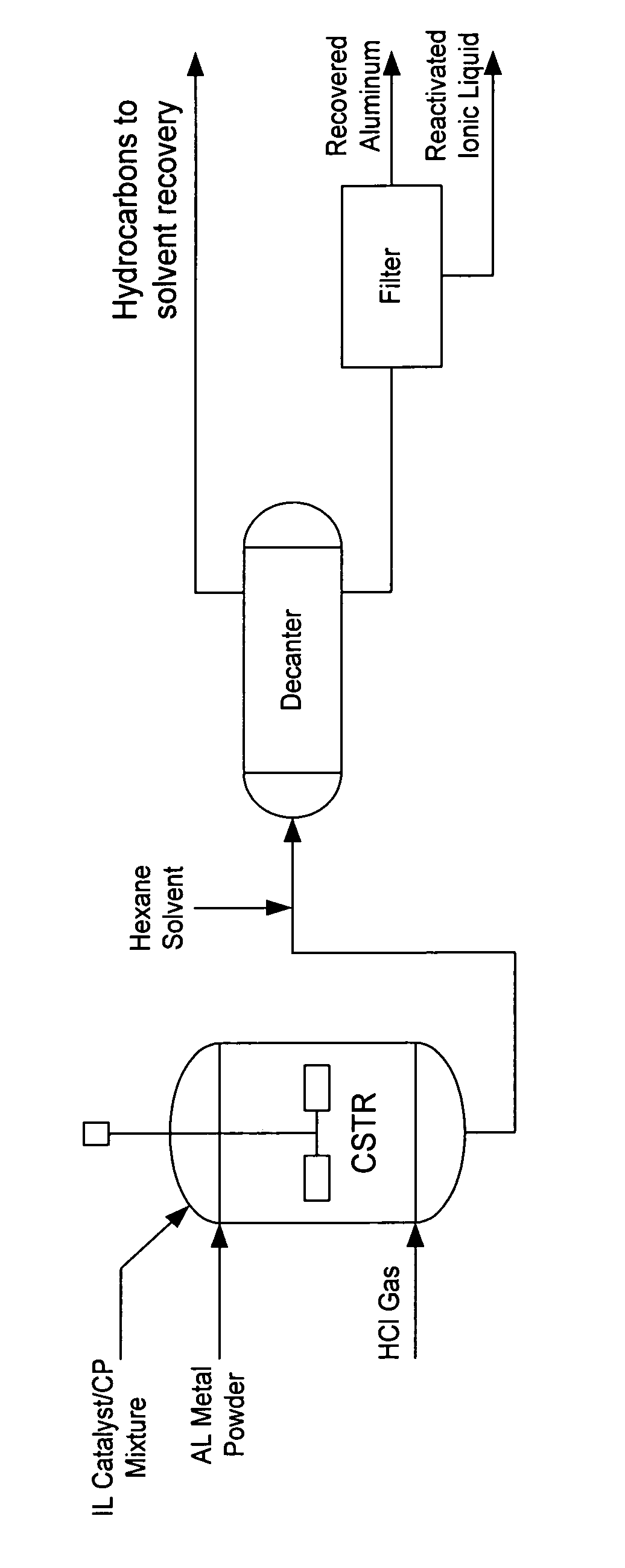
[0013] In one embodiment, the present invention provides a process for regenerating a used acidic ionic liquid catalyst which has been deactivated by conjunct polymers comprising the steps of combining the used ionic liquid catalyst, a metal and HCl in a reaction zone under hydrogenation conditions for a time sufficient to hydrogenate at least a portion of the conjunct polymer; removing reaction product from the reaction zone; mixing the removed reaction product with a hydrocarbon solvent in which the hydrogenated conjunct polymers are soluble; allowing the mixture to separate into two phases, a lighter phase which contains the hydrogenated conjunct polymers and a denser phase which contains a regenerated ionic liquid catalyst; and recovering at least a portion of the heavier phase.

Problems solved by technology

As a result of use, ionic liquid catalysts become deactivated, i.e. lose activity, and may eventually need to be replaced.
However, ionic liquid catalysts are expensive and replacement adds significantly to operating expenses by in some cases requiring shut down of an industrial process.
One of the heretofore unsolved problems impeding the commercial use of chloroaluminate ionic liquid catalysts has been the inability to regenerate and recycle them.

Method used


Image

  • Regeneration of ionic liquid catalyst by hydrogenation using metal and acid
  • Regeneration of ionic liquid catalyst by hydrogenation using metal and acid
  • Regeneration of ionic liquid catalyst by hydrogenation using metal and acid

Examples


example 1

Preparation of Fresh 1-Butylpyridinium Chloroaluminate Ionic Liquid Catalyst A (Fresh IL A)

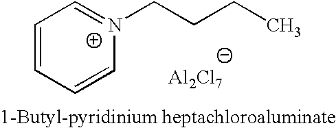
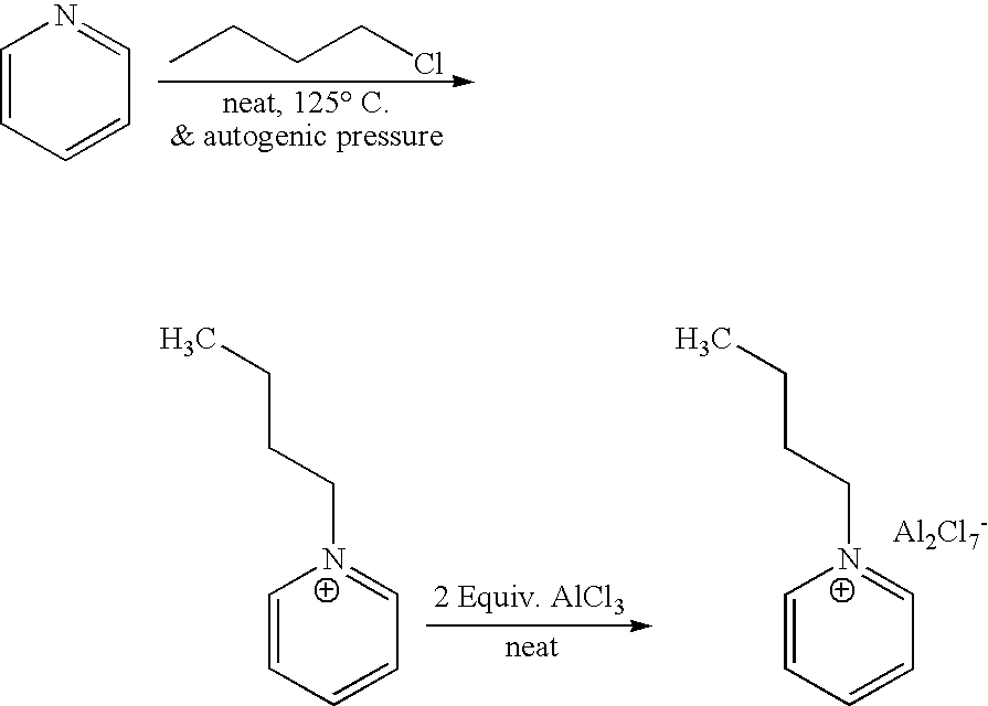
[0035] 1-butyl-pyridinium chloroaluminate is a room temperature ionic liquid prepared by mixing neat 1-butyl-pyridinium chloride (a solid) with neat solid aluminum trichloride in an inert atmosphere. The syntheses of butylpyridinium chloride and the corresponding 1-butyl-pyridinium chloroaluminate are described below. In a 2-L Teflon-lined autoclave, 400 gm (5.05 mol.) anhydrous pyridine (99.9% pure purchased from Aldrich) were mixed with 650 gm (7 mol.) 1-chlorobutane (99.5% pure purchased from Aldrich). The autoclave was sealed and the neat mixture allowed to stir at 125° C. under autogenic pressure over night. After cooling off the autoclave and venting it, the reaction mix was diluted and dissolved in chloroform and transferred to a three liter round bottom flask. Concentration of the reaction mixture at reduced pressure on a rotary evaporator (in a hot water bath) to remove excess chlori...

example 2

Preparation of “Deactivated” 1-Butylpyridinium Chloroaluminate Ionic Liquid Catalyst (Deactivated Catalyst A)

[0037]“Deactivated” or “used” 1-butylpyridinium chloroaluminate ionic liquid catalyst was prepared from “fresh” 1-butylpyridinium chloroaluminate ionic liquid catalyst by carrying out the isobutane alkylation reaction in a continuous flow microunit under catalyst recycle with accelerated fouling conditions.

[0038] The microunit consists of feed pumps for isobutane and butenes, a stirred autoclave reactor, a back pressure regulator, a three phase separator, and a third pump to recycle the separated ionic liquid catalyst back to the reactor. The reactor was operated at 80 to 100 psig pressure and with cooling to maintain a reaction temperature of ˜10° C. To start the reaction, isobutane, butenes, and HCl were pumped into the autoclave at the desired molar ratio (isobutane / butenes>1.0), through the back pressure regulator, and into the three phase separator. At the same time, f...

example 3

Determination of the Amounts of Conjunct Polymer And Olefin Oligomers In Deactivated IL A

[0041] The wt % of conjunct polymers in the spent (deactivated) ionic liquid was determined by hydrolysis of known weights of the spent catalyst. The example below is a typical procedure for measuring conjunct polymers in a given spent catalyst. In a glove box, 15 gm of a spent ionic liquid catalyst in a flask were rinsed first with 30-50 ml of anhydrous hexane to remove (from the spent catalyst) any residual hydrocarbon or olefinic oligomers. The hexane rinse was concentrated under reduced pressure to give only 0.02 gm of yellow oil (0.13%). Then, 50 ml of anhydrous hexane was added to the rinsed catalyst followed by slow addition of 15 ml of water, and the mixture was stirred at 0° C. for 15-20 minutes. The resulting mixture was diluted with additional 30 ml hexanes and stirred well for additional 5-10 minutes. The mixture was allowed to settle down to two layers solution and some solid resid...


PUM

PropertyMeasurementUnit
temperaturesaaaaaaaaaa
temperatureaaaaaaaaaa
pressuresaaaaaaaaaa

Abstract

A process for regenerating a used acidic ionic liquid catalyst which has been deactivated by conjunct polymers comprising combining the used catalyst, a metal and a Broensted acid which acts a source of hydrogen in a reaction zone under hydrogenation conditions for a time sufficient to hydrogenate at least a portion of the conjunct polymer is disclosed. An embodiment of a process for regenerating a used acidic ionic liquid catalyst which has been deactivated by conjunct polymers comprising the steps of combining the used ionic liquid catalyst, a metal and HCl in a reaction zone under hydrogenation conditions for a time sufficient to hydrogenate at least a portion of the conjunct polymer; removing reaction product from the reaction zone; mixing the removed reaction product with a hydrocarbon solvent in which the hydrogenated conjunct polymers are soluble; allowing the mixture to separate into two phases, a lighter phase which contains the hydrogenated conjunct polymers and a heavier phase which contains a regenerated ionic liquid catalyst; and recovering at least a portion of the heavier phase is also disclosed.

Description

FIELD OF THE INVENTION [0001] The present invention relates to methods for the regeneration of catalysts and more specifically to the regeneration of ionic liquid catalysts. BACKGROUND OF THE INVENTION [0002] Ionic liquids are liquids that are composed entirely of ions. The so-called “low temperature” Ionic liquids are generally organic salts with melting points under 100 degrees C., often even lower than room temperature. Ionic liquids may be suitable for example for use as a catalyst and as a solvent in alkylation and polymerization reactions as well as in dimerization, oligomerization acetylation, metatheses, and copolymerization reactions. [0003] One class of ionic liquids is fused salt compositions, which are molten at low temperature and are useful as catalysts, solvents and electrolytes. Such compositions are mixtures of components which are liquid at temperatures below the individual melting points of the components. [0004] Ionic liquids can be defined as liquids whose make-...

Claims


Application Information

Patent Timeline
Patent Type & Authority Applications(United States)
IPC IPC(8): B01J27/125B01J27/06B01J31/00
CPCB01J27/125B01J27/32B01J31/0278B01J31/0284B01J31/0287B01J31/0288B01J31/40C07C2/862Y02P20/584B01J38/60B01J38/62B01J21/20B01J38/48
Inventor ELOMARI, SALEHHARRIS, THOMAS V.
Owner CHEVROU USA INC
Learn More