
Method and circuit for generating random numbers, and computer program product therefor

a random number and computer program technology, applied in the field of random number generators, can solve the problems of not ensuring a specified output bit rate, bit rate itself is not very high, and trngs are unsuitable for applications such as simulations, real-time cryptography e.g. in telecommunications, and achieve the effect of greater security

Active Publication Date: 2007-06-21
TELECOM ITALIA SPA
View PDF11 Cites 25 Cited by
  • Summary
  • Abstract
  • Description
  • Claims
  • Application Information

AI Technical Summary

Benefits of technology

The invention provides a high-speed random number generator that uses both true and pseudo-random numbers to create a secure and unpredictable output. The generator includes a true random number generator, a pseudo-random number generator, and a mixing logic that alters the behavior of the pseudo-random number generator using the random seeds. The invention also provides a method of generating random numbers by altering a pseudo-random sequence using true random numbers and an alteration signal. The invention offers greater security and efficiency compared to previous random number generators.

Problems solved by technology

The main problem with such generators is that, being the physical principle on which they are based actually random, they do not guarantee a specified output bit rate and the bit rate itself is not very high.
This makes TRNGs unsuitable for applications like simulations, real-time cryptography e.g. in telecommunications, etc.
In other cases, e.g. cryptography and security applications, the possibility of recovering the seed, even with a considerable effort, is of course a weakness in the security chain.
The device disclosed in that document cannot obtain high bit rates and, moreover, it exploits only one randomness factor, i.e. the random value of the TRNG sequence.
Thus, all such prior proposals for modifying the behaviour of the pseudo-random generator are based on techniques that use a single randomness factor, so that they are rather simple and do not guarantee a good and deep interaction with the PRNG.

Method used


Image

  • Method and circuit for generating random numbers, and computer program product therefor
  • Method and circuit for generating random numbers, and computer program product therefor
  • Method and circuit for generating random numbers, and computer program product therefor

Examples


Embodiment Construction

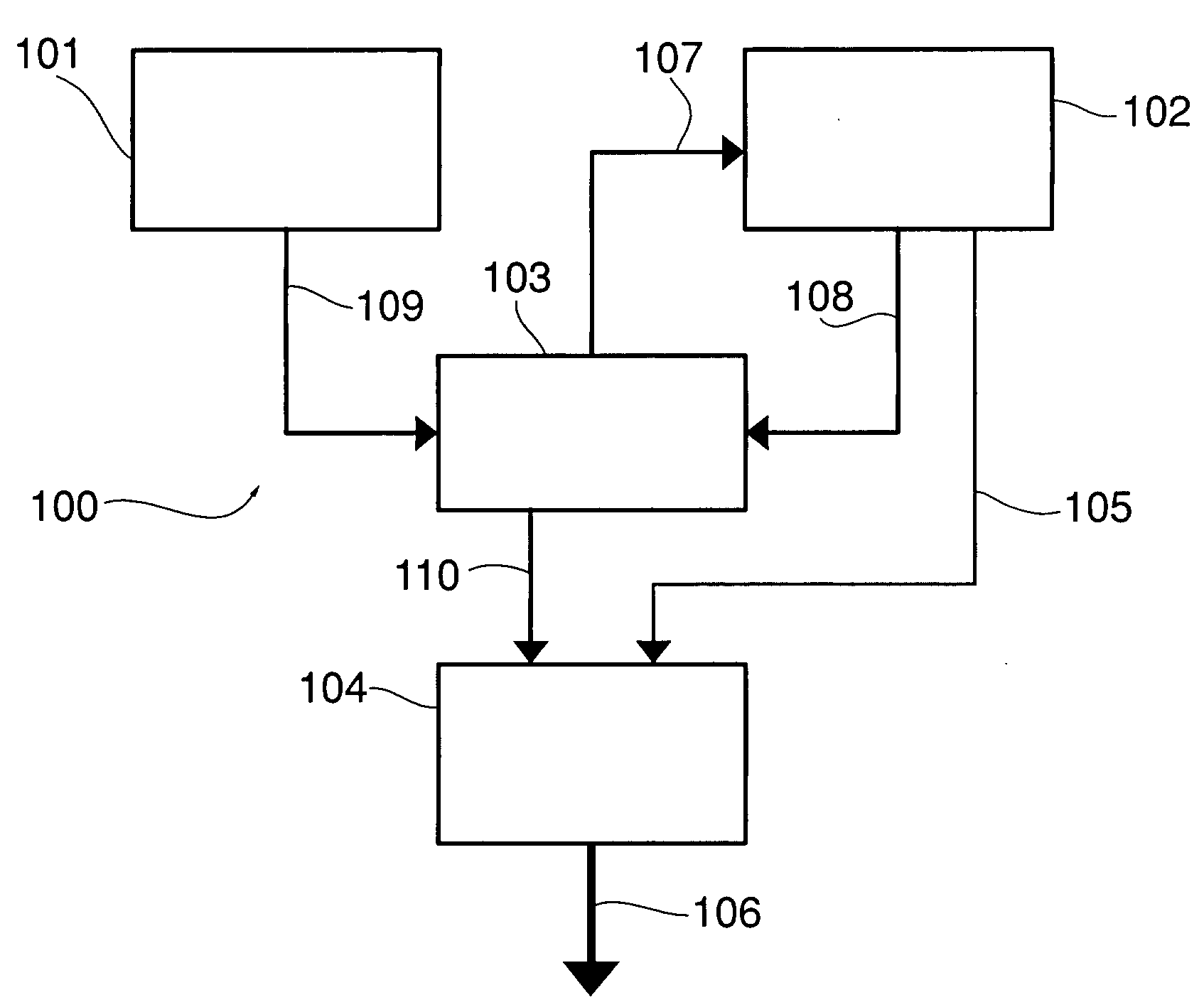
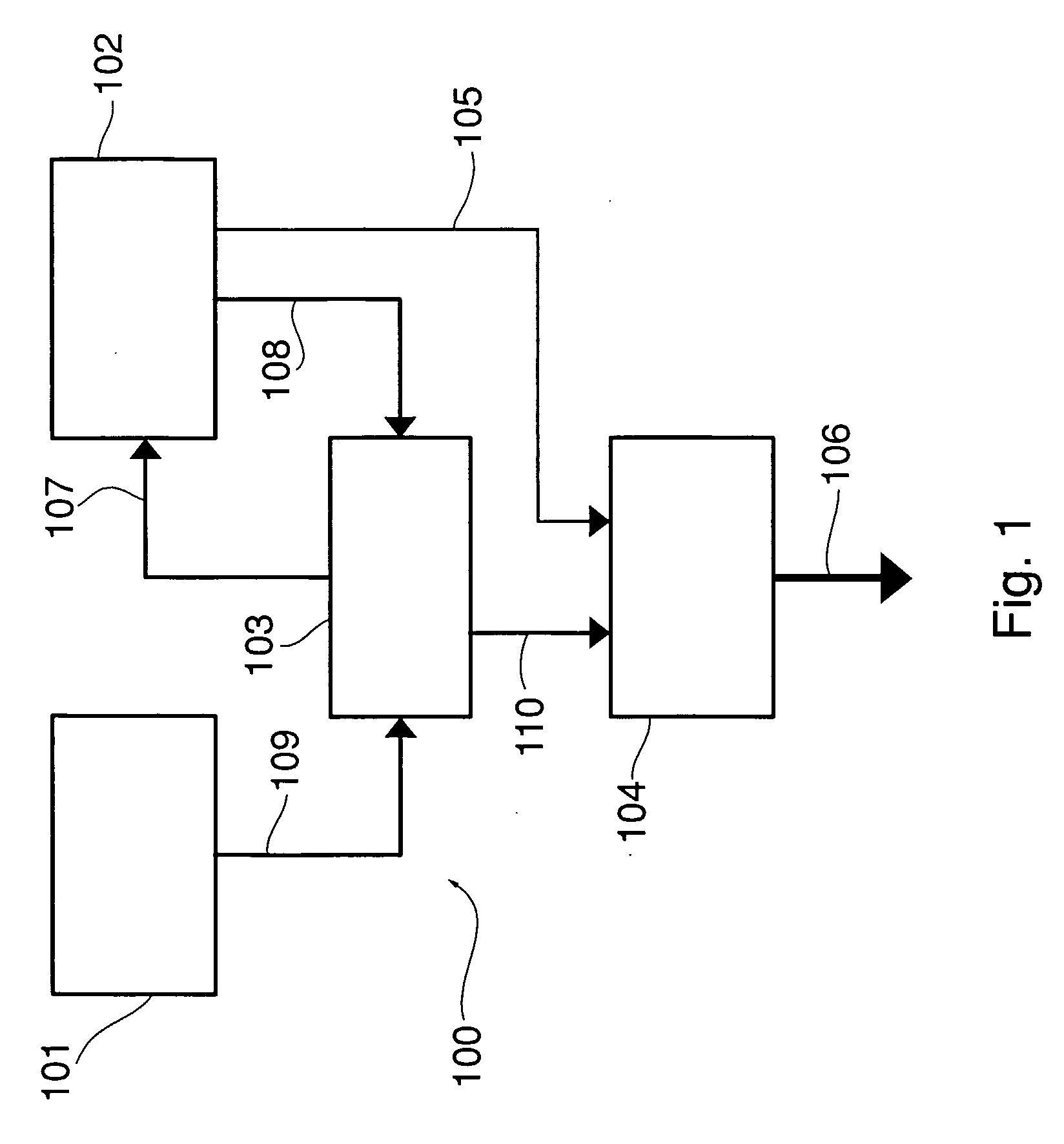
[0024]FIG. 1 shows the main functional blocks of the high speed random number generator according to the invention, generally denoted 100. Like the prior art generators mentioned above, generator 100 is based on the use of a True Random Number Generator (TRNG) 101 and a Pseudo-Random Number Generator (PRNG) 102.

[0025] TRNG 101 is the source of a sequence of random bits with variable bit rate, i.e. variable inter-arrival time, from which a random seed for the sequence generated by PRNG 102 is built. A mixing logic 103 receives the output sequence of TRNG 101, present on line 109, and obtains therefrom the random seed to be applied to PRNG 102 to introduce random alterations in its behaviour. An output logic 104 receives the serial stream issued by PRNG 102 on line 105 and provides a parallel output on line 106 by converting the 1-bit signal into words having a desired length. Output logic 104 may be controlled by mixing logic 103, as schematised by line 110, as explained in detail h...


PUM


Abstract

A random number generator uses the output of a true random generator to alter the behavior of a pseudo-random number generator. The alteration is performed by a mixing logic that builds a random seed for the pseudo-random number generator and includes a generator of an alteration signal, the generation of which exploits the random instant of arrival of the bits outgoing from the true random generator. The alteration signal is obtained by processing the seed by means of the pseudo-random sequence.

Description

FIELD OF THE INVENTION [0001] The present invention relates to random number generators that could be implemented in digital integrated circuits like Application Specific Integrated Circuits (ASICs) and Field Programmable Gate Arrays (FPGAs), and more particularly it concerns a high speed random number generator of the kind in which a pseudo-random number generator uses as seed the random numbers generated by a true random number generator. BACKGROUND OF THE INVENTION [0002] A lot of applications, like simulation, gaming, statistics, cryptography and generally security applications, etc., require use of random number generators. [0003] Generally, existing random number generators can be subdivided into two main categories: hardware-based generators and software-based generators. [0004] Hardware-based generators, commonly referred to as True Random Number Generators (TRNG), exploit randomly occurring physical phenomena like electrical noise, oscillator jitter, flip-flop metastability...

Claims


Application Information

Patent Timeline
Patent Type & Authority Applications(United States)
IPC IPC(8): H04L9/00G06F7/58
CPCG06F7/584G06F7/588H04L9/0861H04L9/0662
Inventor GHIGO, GIOVANNIBOLLEA, LORIS
Owner TELECOM ITALIA SPA
Learn More