
Sealing member for fuel cell, fuel cell, and method of manufacturing the fuel cell

a technology of sealing member and fuel cell, which is applied in the direction of cell components, final product manufacturing, sustainable manufacturing/processing, etc., can solve the problems of inability to completely prevent gas leakage of oxygen gas and hydrogen gas, the possibility of breaking the polymer electrolyte membrane, and the overall safety is not guaranteed

Inactive Publication Date: 2007-06-14
SAMSUNG SDI CO LTD
View PDF8 Cites 37 Cited by
  • Summary
  • Abstract
  • Description
  • Claims
  • Application Information

AI Technical Summary

Benefits of technology

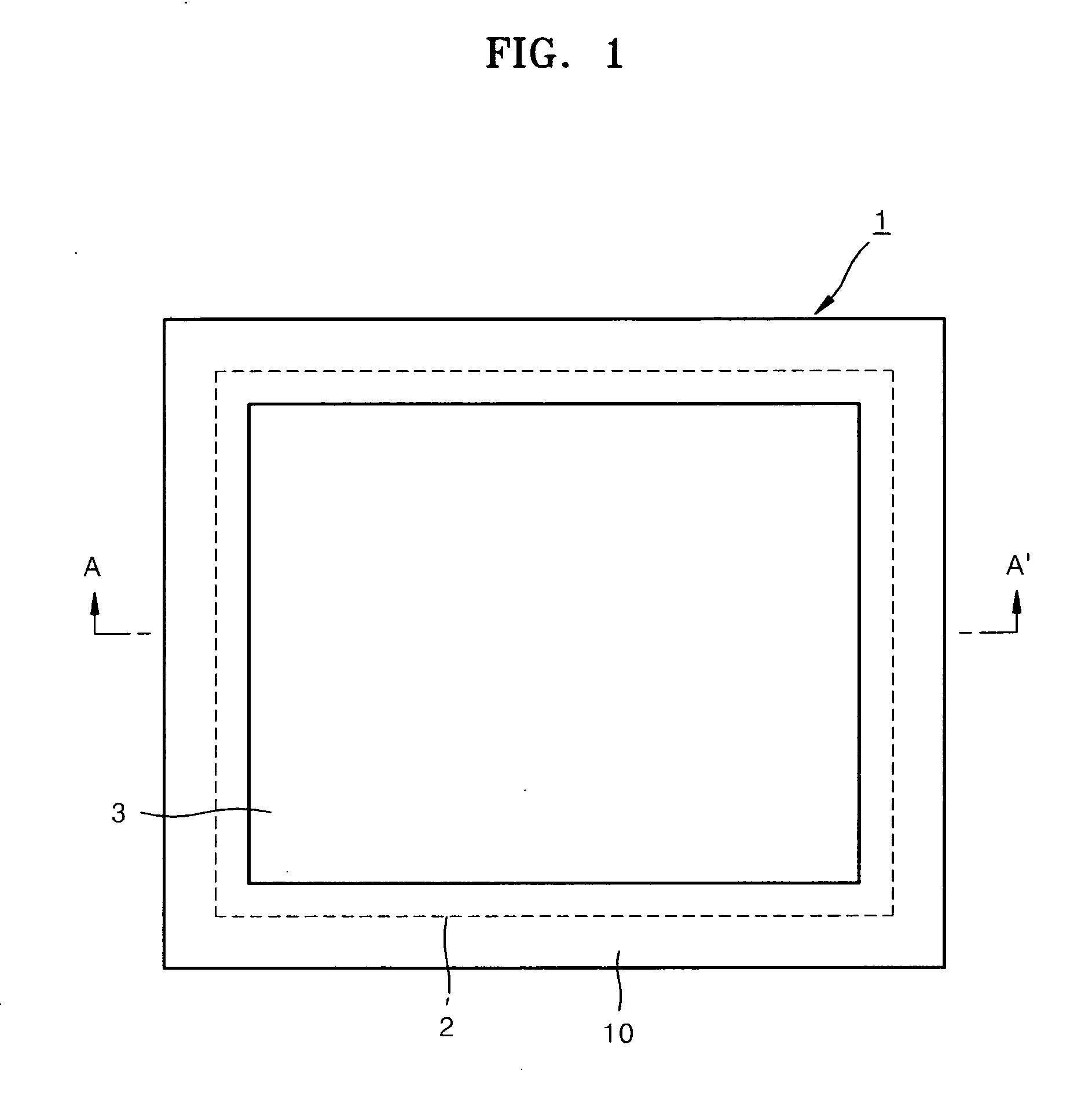
[0011] Aspects of the present invention provide a sealing member that can prevent a gas leakage from unit cell and a gas leakage from the unit cell itself, a fuel cell having the sealing member, and a method of manufacturing the fuel cell.
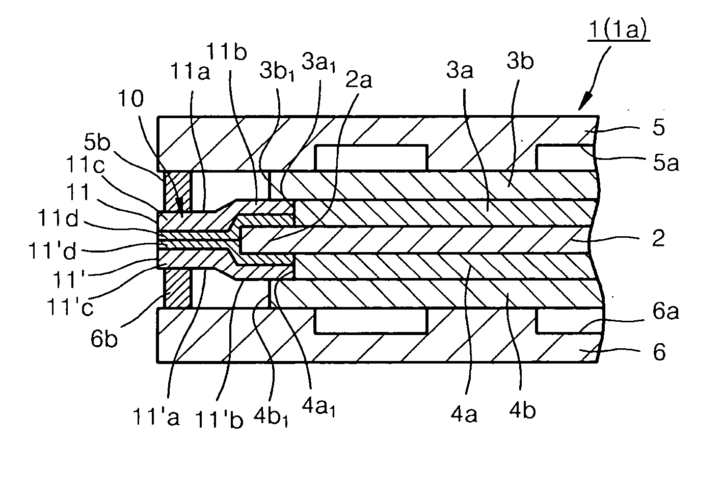
[0014] According to the above configuration, the belts that constitute the sealing member may include non-gas transmitting layers formed of aromatic polyimide or aluminum. Therefore, gas leakage transmitting through the belts can be blocked, and in particular, the gas leakage in a unit cell of a fuel cell can be prevented. Also, since outer edge portions of the belts are thermally bonded to each other, gas leakage through the belts can be prevented, and in particular, the gas leakage in a unit cell of a fuel cell can be prevented.
[0020] According to the above configuration, the belts that constitute the sealing member include non-gas transmitting layers formed of aromatic polyimide or aluminum. Therefore, gas leakage from an electrode to the other electrode can be blocked by the belts, and in particular, the gas leakage in a unit cell of a fuel cell can be prevented. Also, since outer edge portions of the belts are thermally bonded to each other, gas leakage through or between the belts can be prevented, and in particular, the gas leakage in a unit cell of a fuel cell can be prevented.
[0021] Also, since the edge portion of the electrolyte membrane is inserted between the inner edge portions of the belts and the outer edge portions of the belts are thermally bonded to each other, the gas leakage transmitting through the electrolyte membrane can be completely blocked.
[0024] According to the above configuration, since the outer edge portions of the belts are thermally bonded after the belts overlap the edge portion of the electrolyte membrane, a fuel cell in which the electrolyte membrane is held between the inner edge portions of the belts and wherein the outer edge portions of the belts are thermally bonded can be manufactured. Therefore, gas leakage from an electrode to the other electrode can be blocked by the belts, and gas leakage in a unit cell of a fuel cell can be prevented. Also, since the outer edge portions of the belts are thermally bonded to each other, gas leakage through the belts can be prevented, and gas leakage in a unit cell of a fuel cell can be prevented. Also, since the edge portion of the electrolyte membrane is held between the inner edge portions of the belts and since the outer edge portions of the belts are thermally bonded, gas leakage through the electrolyte membrane can be completely blocked.

Problems solved by technology

However, when the sealing structure of the fuel cell disclosed in Japanese Patent Publication No. 2005-108565 is applied to a fuel cell having a polymer electrolyte membrane, gas leakage of oxygen gas and hydrogen gas cannot be completely prevented.
That is, if the polymer electrolyte membrane does not have certain strength when the electrolyte membrane is inserted between the pair of gaskets, there is a possibility of breaking the polymer electrolyte membrane.
However, if the sealing members are not bonded as one unit, there is a possibility of gas leakage due to gaps between the sealing members and thus, overall safety is not ensured.
In such a case, when the sealing members are tightened using a screw when a unit cell is manufactured, there may be distortions in the sealing members.
Therefore, there is a high possibility in such a structure of leakage of oxygen and hydrogen gases.

Method used


Image

  • Sealing member for fuel cell, fuel cell, and method of manufacturing the fuel cell
  • Sealing member for fuel cell, fuel cell, and method of manufacturing the fuel cell
  • Sealing member for fuel cell, fuel cell, and method of manufacturing the fuel cell

Examples


embodiments

Embodiment 1

[0083] To evaluate the sealing member according to the present invention, a power generation unit cell was manufactured in the following procedure.

[0084] First, a polymer electrolyte membrane in a gel state was obtained by soaking a polybenzimidazole film in 85% phosphoric acid. The doping rate of the phosphoric acid was 450%, and the thickness of the polymer electrolyte membrane was 75 μm. The polymer electrolyte membrane was a square shape having dimensions of 5.4 cm×5.4 cm.

[0085] Electrodes (Vulcan XJ-72 containing 30% of a Pt catalyst formed on carbon paper to a density of 0.5 mg / cm2) manufactured by E-TEK Co. were used as a fuel electrode and oxygen electrode. The fuel electrode and the oxygen electrode both have a square shape having dimensions of 5 cm×5 cm.

[0086] Square shaped (7 cm×7 cm) carbon separators having gas flow channels (grooves) were prepared as separators plates with gas flow channels. Also, current collectors and end plates were prepared. A groov...

embodiment 2

[0091] A unit cell of a fuel cell according to another embodiment of the present invention was manufactured as the same dimensions and materials as the embodiment 1 except that the thickness of each of the thermoplastic resin layers was 5 μm in the experimental embodiment 2.

embodiment 3

[0092] A unit cell of a fuel cell according to another embodiment of the present invention was manufactured with the same dimensions and materials as the experimental embodiment 1 except that the thickness of each of the thermoplastic resin layers was 10 μm in the experimental embodiment 3.


PUM

PropertyMeasurementUnit
Thicknessaaaaaaaaaa
Lengthaaaaaaaaaa
Areaaaaaaaaaaa

Abstract

A sealing member for a fuel cell includes a pair of belts that include non-gas transmitting layers formed of aromatic polyimide or aluminum and thermoplastic resin layers. The belts are disposed such that the thermoplastic resin layers of the belts face each other, and the thermoplastic resin layers in outer edge portions of the belts are thermally bonded to each other. In a fuel cell, an inner portion of the belts engage the electrolyte membrane.

Description

CROSS-REFERENCE TO RELATED APPLICATIONS [0001] This application claims the benefit of Japanese Patent Application No. 2005-348979, filed on Dec. 2, 2005, in the Japanese Intellectual Property Office, the disclosure of which is incorporated herein by reference. BACKGROUND OF THE INVENTION [0002] 1. Field of the Invention [0003] Aspects of the present invention relate to a sealing member for a fuel cell, a fuel cell using the sealing member, and a method of manufacturing the fuel cell. [0004] 2. Description of the Related Art [0005] A fuel cell is a device that generates electrical energy through an oxidation-reduction reaction between an oxygen gas that is supplied to an oxygen electrode and a hydrogen gas that is supplied to a fuel electrode, producing water as a by-product. A fuel cell is formed of a plurality of unit cells that are connected to each other, wherein each of the unit cells includes an electrolyte membrane, an oxygen electrode, and a fuel electrode. [0006] To increase...

Claims


Application Information

Patent Timeline
IPC IPC(8): H01M2/08F16J15/10H01M50/77
CPCH01M8/0273H01M8/0276H01M8/0284Y02E60/50Y02P70/50H01M8/02H01M8/0258
Inventor YUICHI, AIHARASAKAI, KATSUNORI
Owner SAMSUNG SDI CO LTD
Learn More