Wide-band multimode frequency synthesizer and variable frequency divider

a multi-mode frequency synthesizer and variable frequency technology, applied in the direction of oscillator generators, pulse automatic control, pulse technique, etc., can solve the problems of increasing chip size and power consumption, affecting the construction flexibility of frequency synthesizers, and using voltage-controlled oscillators, etc., to reduce the occupied area and electric power consumption

Inactive Publication Date: 2007-06-14
ELECTRONICS & TELECOMM RES INST
View PDF4 Cites 35 Cited by
  • Summary
  • Abstract
  • Description
  • Claims
  • Application Information

AI Technical Summary

Benefits of technology

[0009] The present invention is also directed to a multiband wide-band frequency synthesizer capable of reducing an occupied area and electric power consumption by using a multimode prescaler.

Problems solved by technology

However, use of a voltage-controlled oscillator, a high speed prescaler, a charge pump, and a loop filter diminishes flexibility in the construction of the frequency synthesizer.
However, using a plurality of voltage-controlled oscillators and PLL loops results in increased chip size and power consumption.

Method used


Image

  • Wide-band multimode frequency synthesizer and variable frequency divider
  • Wide-band multimode frequency synthesizer and variable frequency divider
  • Wide-band multimode frequency synthesizer and variable frequency divider

Examples


Embodiment Construction

[0022] Hereinafter, exemplary embodiments of the present invention will be described in detail. However, the present invention is not limited to the embodiments disclosed below, but can be implemented in various forms. Therefore, the following embodiments are described in order for this disclosure to be complete and fully enabling of practice of the present invention by those of ordinary skill in the art.

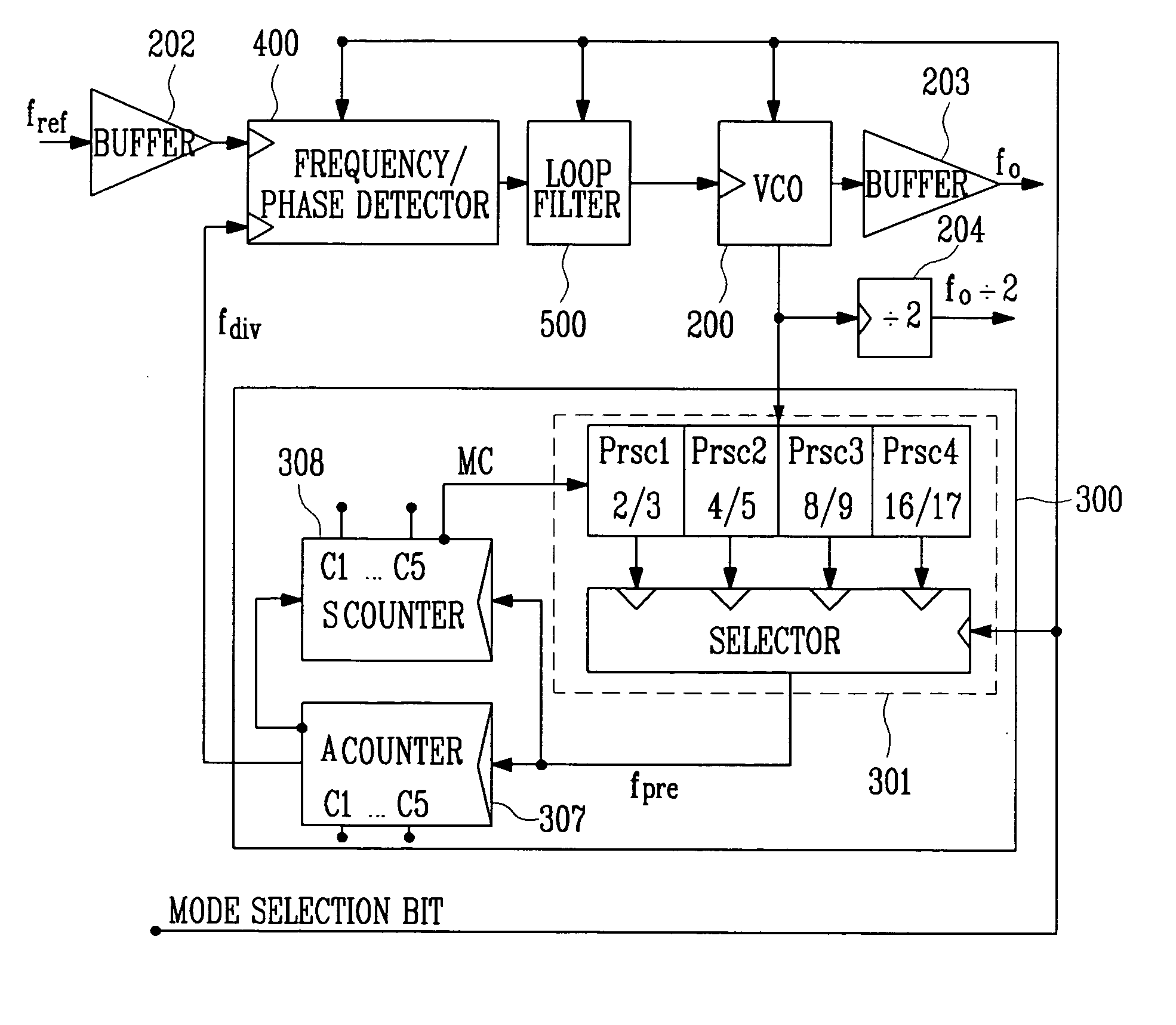
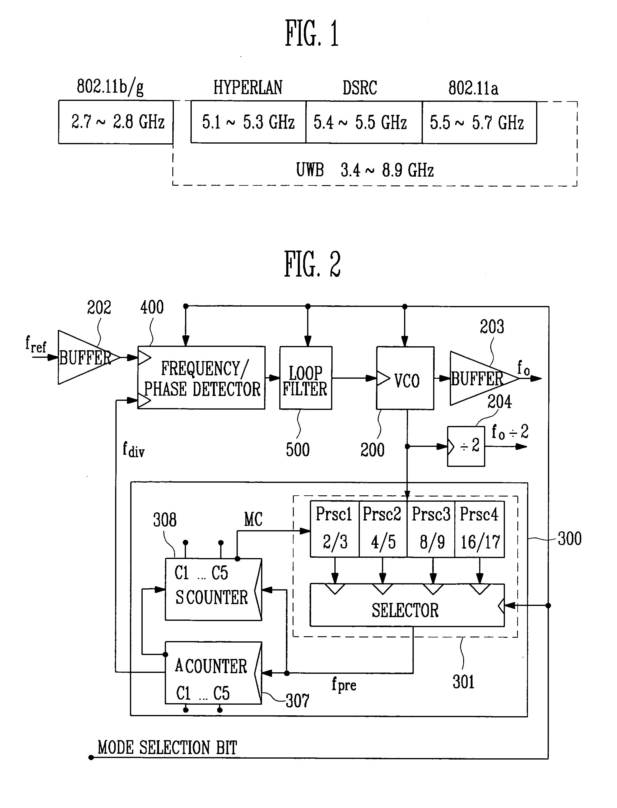
[0023] A frequency synthesizer illustrated in FIG. 2 includes a frequency / phase detector for comparing the frequency and phase of a reference high-frequency signal with the frequency and phase of a feedback high-frequency signal; a charge pump 400 for producing a current corresponding to the result of the comparison by the frequency / phase detector; a loop filter 500 for producing a voltage corresponding to an accumulated value of the output current of the charge pump; a voltage-controlled oscillator 200 for generating an oscillation signal having a frequency corresponding to the ou...


PUM


Abstract

A wide-band multimode frequency synthesizer using a Phase Locked Loop (PLL) is provided. The multiband frequency synthesizer includes a multimode prescaler, a phase detector / a charge pump, a swallow type frequency divider, and a switching bank LC tuning voltage-controlled oscillator having wide-band and low phase noise characteristics. The multimode prescaler operates in five modes and divides a signal up to 12 GHz. The wide-band frequency synthesizer can be used in various fields such as WLAN / HYPERLAN / DSRC / UWB systems that operate in the frequency range from 2 GHz to 9 GHz. The wide-band multimode frequency synthesizer includes a frequency / phase detector for comparing a frequency and phase of a reference high-frequency signal with a frequency and phase of a feedback high-frequency signal; a charge pump for producing an output current corresponding to the result of the comparison performed by the frequency / phase detector; a loop filter for producing an output voltage corresponding to an accumulated value of the output current of the charge pump; a voltage-controlled oscillator for generating an oscillation signal having a frequency corresponding to the output voltage of the loop filter; and a variable frequency divider for dividing an output signal of the voltage-controlled oscillator by a designated integer value, and outputting the result as a feedback signal, wherein at lease two of an amount of unit pumping charges of the charge pump, an RLC value of the loop filter, an RLC value of the voltage-controlled oscillator, and a divisor value of the variable frequency divider are controlled according to a band.

Description

CROSS-REFERENCE TO RELATED APPLICATION [0001] This application claims priority to and the benefit of Korean Patent Application Nos. 2005-119530, filed Dec. 8, 2005, and 2006-74089, filed Aug. 7, 2006, the disclosures of which are incorporated herein by reference in their entirety. BACKGROUND [0002] 1. Field of the Invention [0003] The present invention relates to a multimode frequency synthesizer using a phase-locked loop (PLL) that can be installed in 802.11 b / g HYPERLAN (HIgh PErformance Radio LAN), Dedicated Short Range Communications (DSRC), 802.11 a, and Ultra Wide Band (UWB) systems having applications in a 2˜9 GHz frequency band. [0004] 2. Discussion of Related Art [0005] Recently, as mobile communication services are becoming increasingly widespread, available frequency bands are becoming saturated, and several terminals are required to enjoy various mobile communication services. As a result, developers all over the world are working on a reconfigurable mobile communication...

Claims


Application Information

Patent Timeline
IPC IPC(8): H03L7/085
CPCH03K23/667H03L7/0898H03L7/093H03L7/099H03L7/193H03L7/16
Inventor LEE, JA YOLKIM, KWI DONGKWON, CHONG KIKIM, JONG DAELEE, SANG HEUNG
Owner ELECTRONICS & TELECOMM RES INST
Why Eureka
Try Eureka