
Gas Supplying unit and substrate processing apparatus

Inactive Publication Date: 2007-06-14
TOKYO ELECTRON LTD
View PDF22 Cites 259 Cited by
  • Summary
  • Abstract
  • Description
  • Claims
  • Application Information

AI Technical Summary

Benefits of technology

[0012] This invention is intended to solve the above problems. The object of this invention is to provide a gas supplying unit for supplying a process gas into a processing container, that is capable of preventing sticking of nickel members under a high temperature, so as to improve a maintenance property of the unit. Another object of the present invention is to provide a substrate processing apparatus including the gas supplying unit.
[0014] According to the present invention, between the joining surfaces of the plurality of nickel members, there is provided the intermediate member for preventing sticking made of a material different from nickel. Thus, the nickel portions are prevented from sticking to each other which might be caused by a high temperature. Since the gas showerhead can be easily disassembled for a maintenance operation, it is easy to clean and inspect an inside thereof. That is, replacement of the members can be avoided, which might be necessary when the maintenance operation cannot be performed.

Problems solved by technology

That is, when the gas showerhead is used at a temperature of 420° C. or higher, there might be concern that the “sticking” phenomenon occurs, depending on manners of the usages and conditions of the joining surfaces.
However, when the sticking phenomenon has occurred, it is impossible to separate the shower-plate 12 and the base member 11 from each other, or a large force is required therefor.
As described above, the sticking phenomenon makes difficult the maintenance operation.
This replacement increases running costs, since the gas showerhead is made of a nickel material.
This is disadvantageous in that a power consumption is increased and the O-ring 15 is deteriorated because of the elevated temperature.
However, since a large amount of heat is released from the base member 11, a large amount of consumption energy is required for cooling.
Moreover, the above gas showerhead has the following problem.
When a plasma process is conducted, there might be a possibility that a radiofrequency from the gas showerhead is applied between the sheath metal and the thermocouple to invite a dielectric breakdown.
This, in turn, may make unstable the temperature control, because a heat generated by induction heating of the insulating material affects the detected temperature value.

Method used


Image

  • Gas Supplying unit and substrate processing apparatus
  • Gas Supplying unit and substrate processing apparatus
  • Gas Supplying unit and substrate processing apparatus

Examples


Embodiment Construction

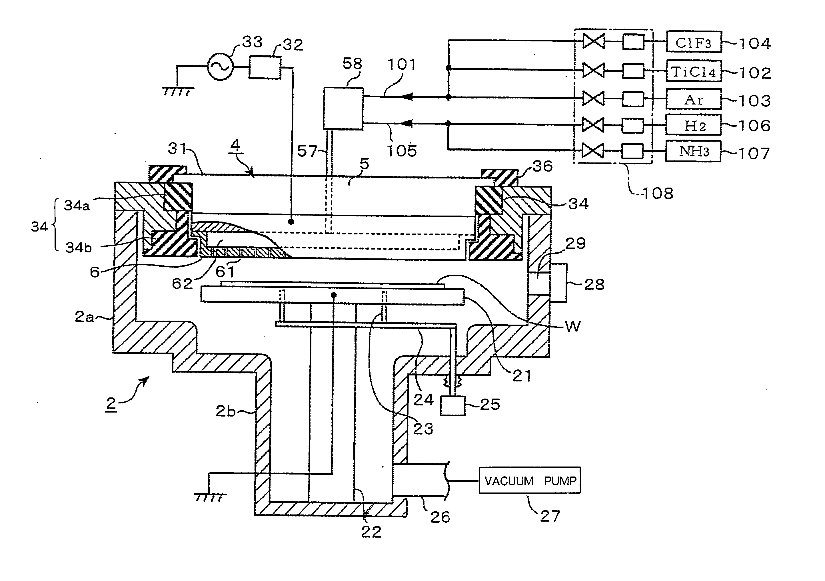
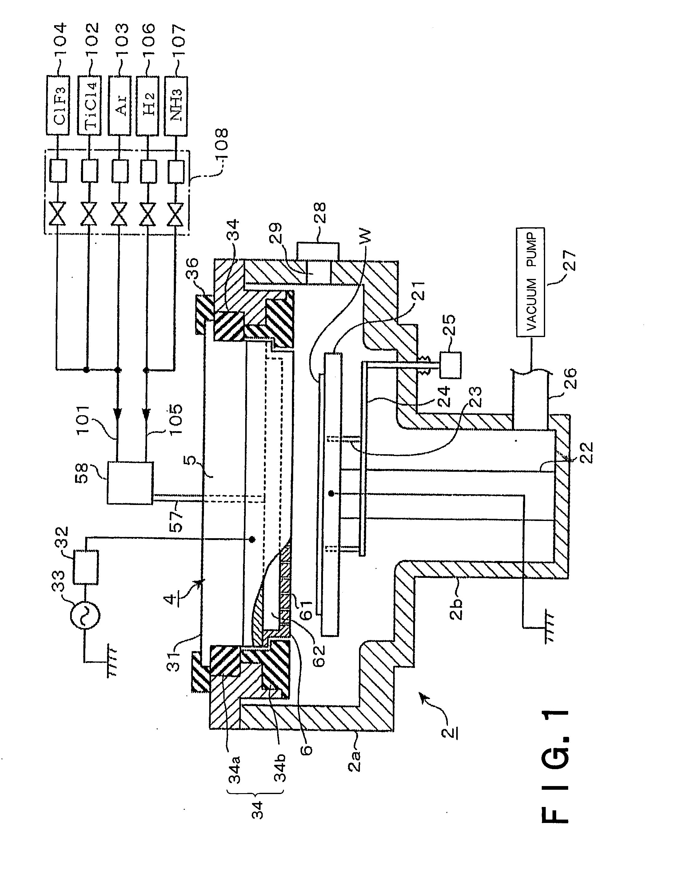
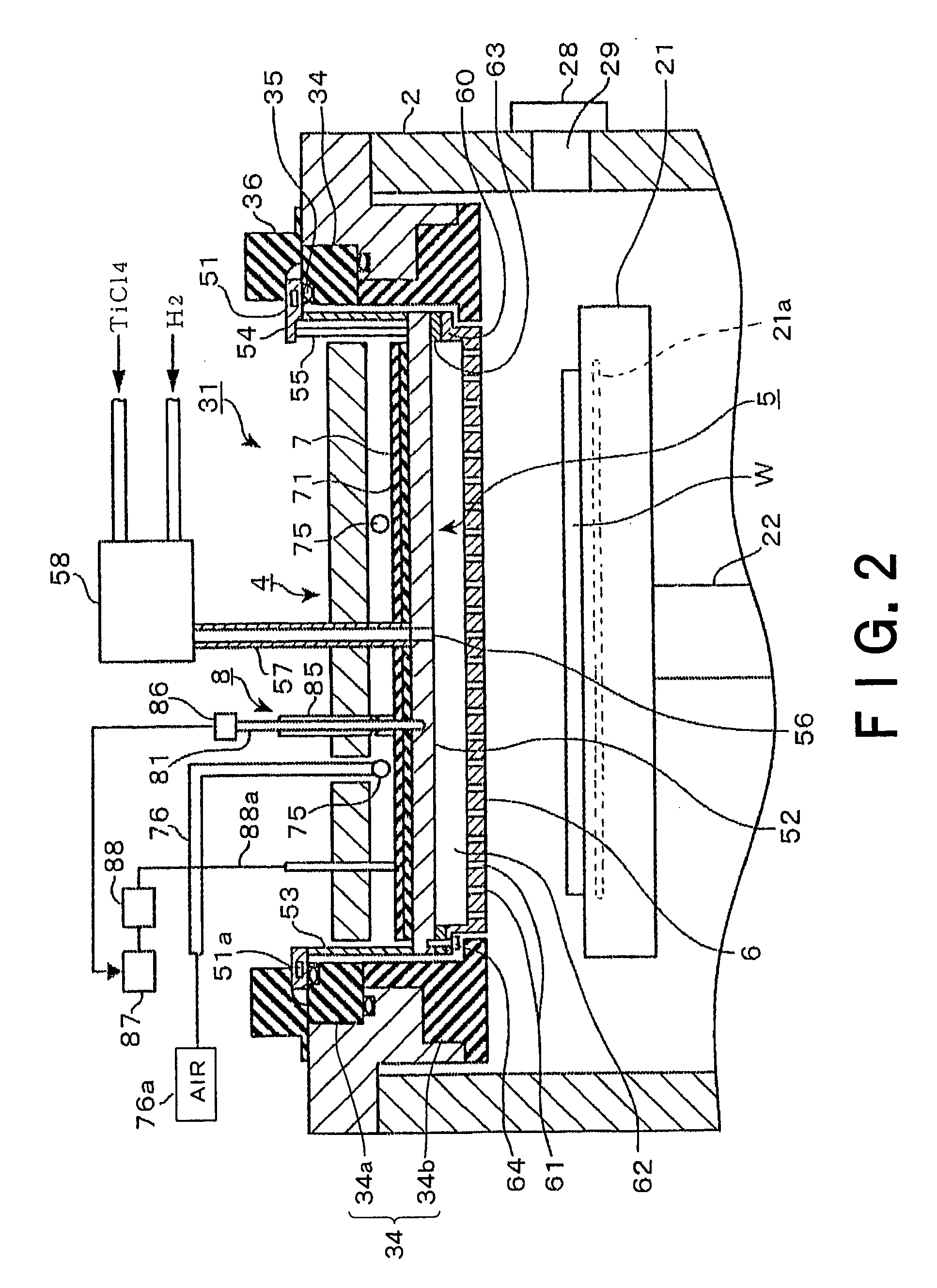
[0040] An embodiment of the present invention will be described below. The gas supplying unit in this embodiment is included in a film-forming apparatus that forms a film by a plasma CVD process.

[0041] The general structure of the film-forming apparatus is described with reference to the schematic sectional view of FIG. 1. In FIG. 1, a processing container 2 is a vacuum chamber made of, e.g., aluminum. An upper part of the processing container 2 is a cylindrical part 2a of a larger diameter, and a lower part of the processing container 2 is a cylindrical part 2b of a smaller diameter. The cylindrical parts 2a and 2b are continuously connected to form a mushroom shape in general. A heating mechanism, not shown, is provided for heating an inner wall of the processing container 2. A stage 21 is arranged in the processing container 2 for horizontally placing thereon a substrate such as a semiconductor wafer (hereinafter referred to as “wafer”) W. The stage 21 is supported on a bottom p...


PUM

PropertyMeasurementUnit
Temperatureaaaaaaaaaa

Abstract

The invention relates to a gas supplying unit to be arranged to hermetically fit in an opening formed at a ceiling part of a processing container for conducting a process to a substrate. The gas supplying unit includes a plurality of nickel members. A large number of gas-supplying holes is formed at a lower surface of the gas supplying unit, a process gas is adapted to be supplied from the large number of gas-supplying holes into the processing container, and the plurality of nickel members is fixed to each other via an intermediate member for preventing sticking made of a material different from nickel.

Description

FIELD OF THE INVENTION [0001] This invention relates to a gas supplying unit that supplies a process gas into a processing container from a large number of gas-supplying holes opposite to a substrate, in order to conduct a predetermined film-forming process to the substrate, and to a substrate processing apparatus including the gas supplying unit. BACKGROUND ART [0002] The film-forming process is one of the semiconductor manufacturing processes. The film-forming process is generally conducted by, e.g., under a vacuum atmosphere, ionizing a process gas to form a plasma thereof or pyrolytically decomposing the process gas to activate the process gas, and depositing active species or reaction products on a surface of a substrate. There is a film-forming process in which a variety of gases are reacted on each other to form a film. For example, a thin film is formed of a metal such as Ti, Cu, and Ta, or a metal compound such as TiN, TiSi, and WSi, or an insulating material such as SiN an...

Claims


Application Information

Patent Timeline
IPC IPC(8): C23C16/00
CPCC23C16/45565C23C16/4557C23C16/45572H01J37/3244H01J37/32449H01L21/3065H01L21/304
Inventor GOMI, HISASHISAITO, TETSUYAKAKEGAWA, TAKASHIMASE, TAKAHISAKOIZUMI, MAKOTOTADA, KUNIHIROWAKABAYASHI, SATOSHINARUSHIMA, KENSAKUCHENG, FANG
Owner TOKYO ELECTRON LTD
Learn More