Method for manufacturing surface-coated cutting insert
a cutting insert and surface coating technology, applied in the field of surface coating cutting insert manufacturing, can solve the problems of reducing the toughness of the insert itself, deteriorating surface roughness, and increasing working energy, and achieve the effect of greatly simplifying the operation and being easy to trea
- Summary
- Abstract
- Description
- Claims
- Application Information
AI Technical Summary
Benefits of technology
Problems solved by technology
Method used
Image
Examples
embodiment 1
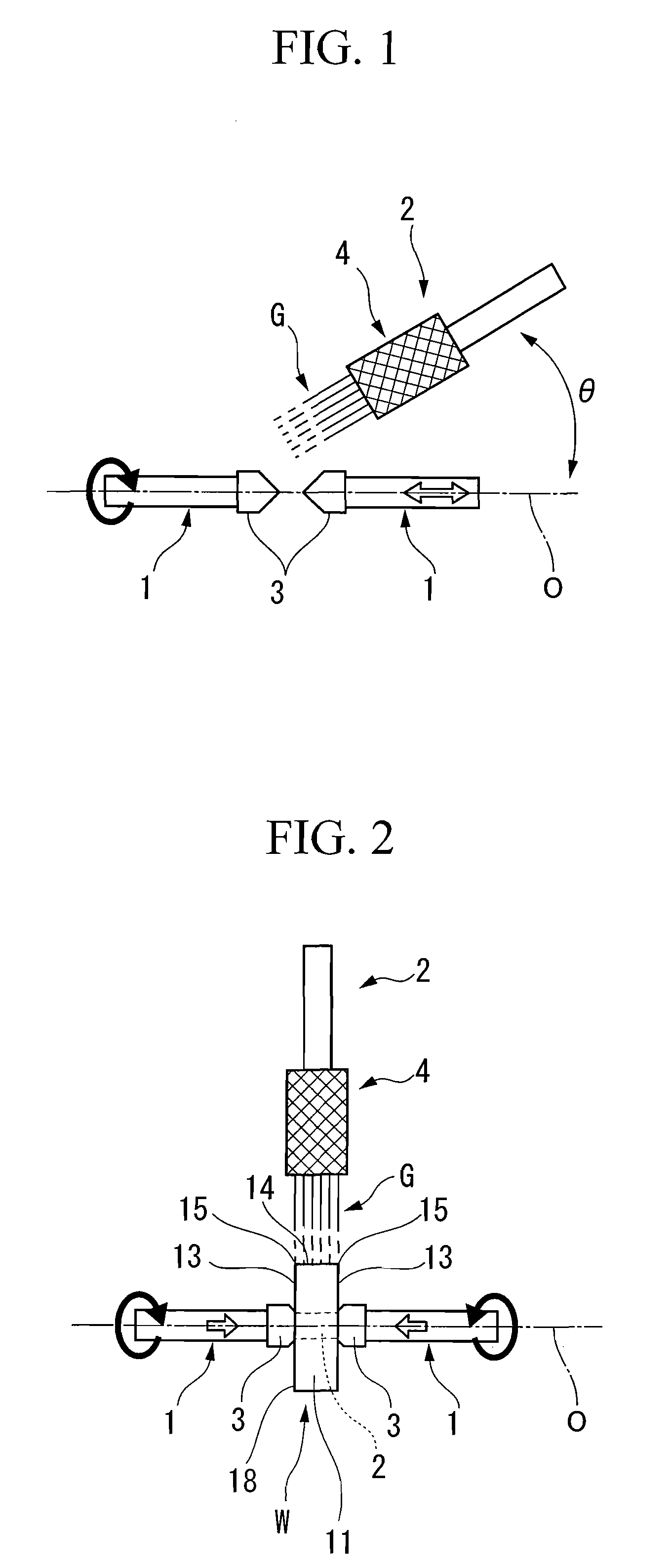
[0046]FIG. 1 shows an example of the equipment for manufacturing a surface-coated cutting insert relating to an embodiment (Embodiment 1) of the present invention, and FIG. 2 shows an embodiment of the present invention using this manufacturing equipment.
[0047] In the manufacturing equipment of FIG. 1, a pair of rotary shafts 1 are located with a spacing therebetween such that their front ends face each other, and are supported coaxially and rotatably in the same direction around an axis extending for example horizontally, and a blasting gun 2 for conducting the wet blasting by jetting an abrasive fluid G to the surface of a surface-coated cutting insert W held between these rotary shafts 1 as shown in FIG. 2 is provided on a side (upper side in FIG. 1) of this axis O.
[0048] Here, an insert body 11 of the surface-coated cutting insert W which is subjected to the wet blasting treatment in this embodiment is formed in the shape of a polygonal plate (the shape of a rhombic plate in FI...
embodiment 2
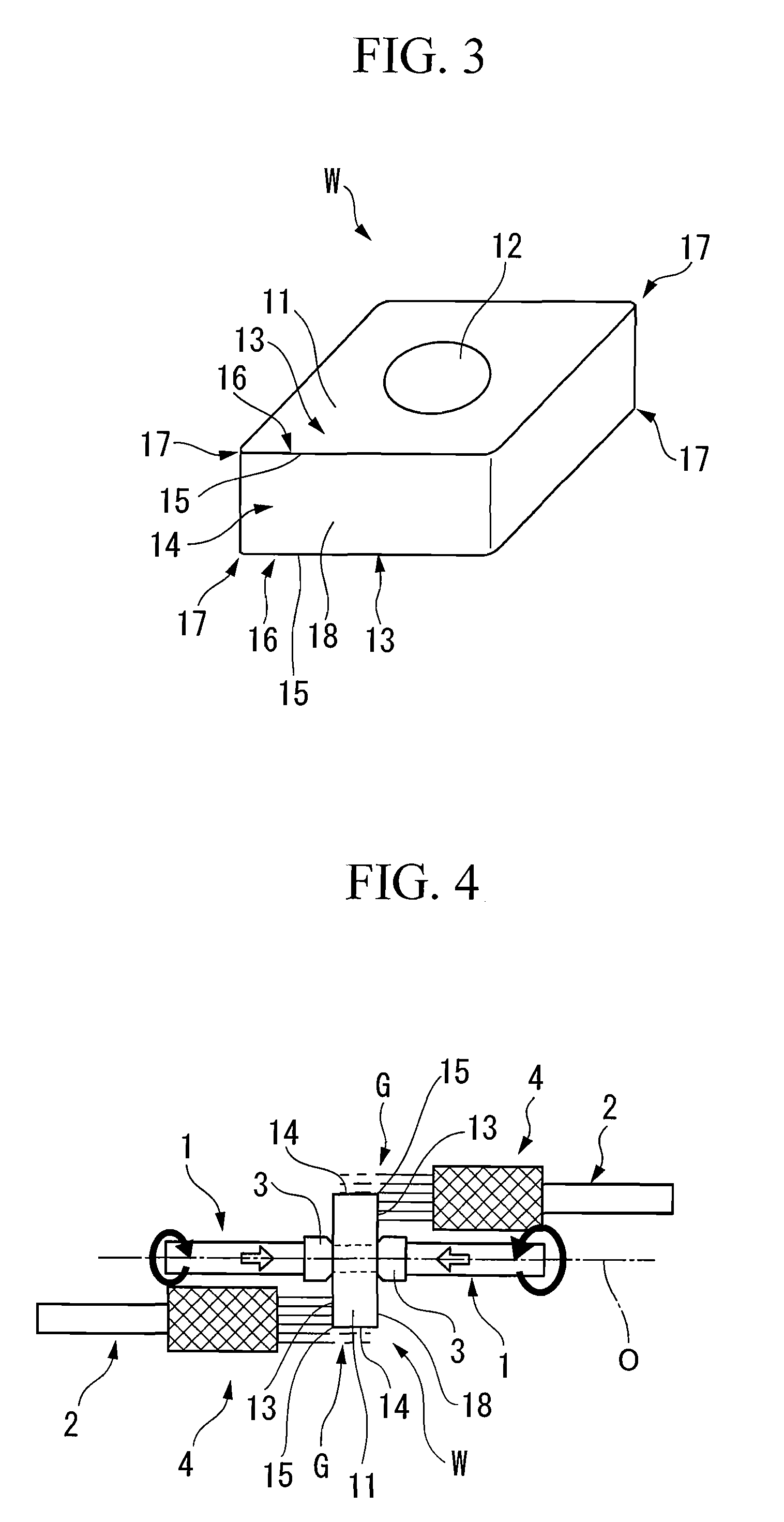
[0069] In this embodiment, the wet blasting treatment is mainly applied to the flank face 14 of the cutting insert W by one blasting gun 2 with the jetting angle of 90°. However, the wet blasting treatment of the rake faces 13 formed at the polygonal faces of the cutting insert and portions on the rake face 13 side at the intersecting edge line regions 15 may also be conducted by adjusting this jetting angle θ and setting it to 0°, i.e., setting it such that the axis O of the rotary shafts 1 and the jetting direction of the abrasive fluid G from the blasting gun 2 are parallel like Embodiment 2 shown in FIG. 4. In the manufacturing equipment relating to this embodiment, a plurality of (two in this embodiment) blasting guns 2 are located on the opposite sides by interposing the axis O of the rotary shafts 1, and are also located on the opposite sides in the direction of the axis O by interposing a portion between a pair of the rotary shafts 1 holding the cutting insert W. Namely, the...
embodiment 3
[0071] In the manufacturing method of the present invention based on such a manufacturing equipment, the blasting gun 2 may also be arranged by adjusting the jetting angle θ so that it makes an acute angle of more than 0° and less than 90° with the axis O, like Embodiment 3 shown in FIG. 5 (45° in FIG. 5), in addition to the embodiments shown in FIG. 2 and FIG. 4. In this case, the intersecting edge line region 15, the flank face 14 of cutting insert W which crosses at this intersecting edge line region 15 and the rake face 13 which is formed on one polygonal face of the insert body 11 can be simultaneously treated, for example, by conforming the central line of jetting of the abrasive fluid G from a blasting gun 2 to the vicinity of the intersecting edge line region 15. Accordingly, like the above embodiment, the entire surface of the cutting insert W can be subjected to wet blasting treated simultaneously and more efficiently with the rotation of rotary shafts 1 by arranging a plu...
PUM
| Property | Measurement | Unit |
|---|---|---|
| Pressure | aaaaa | aaaaa |
| Angle | aaaaa | aaaaa |
| Shape | aaaaa | aaaaa |
Abstract
Description
Claims
Application Information
 - R&D
- Intellectual Property
- Life Sciences
- Materials
- Tech Scout
- Unparalleled Data Quality
- Higher Quality Content
- 60% Fewer Hallucinations
Browse by: Latest US Patents, China's latest patents, Technical Efficacy Thesaurus, Application Domain, Technology Topic, Popular Technical Reports.
© 2025 PatSnap. All rights reserved.Legal|Privacy policy|Modern Slavery Act Transparency Statement|Sitemap|About US| Contact US: help@patsnap.com


