Crawler, crawler pin, crawler bush, and crawler manufacturing method
a manufacturing method and technology for crawlers, applied in the direction of ring springs, vehicle cleaning, driving chains, etc., can solve the problems of crawler bush breaking more frequently, seizure cannot be avoided, etc., to improve the long-term holdability of the above grease or lubricating oil, and the lifetime of the crawler is easily shortened
- Summary
- Abstract
- Description
- Claims
- Application Information
AI Technical Summary
Benefits of technology
Problems solved by technology
Method used
Image
Examples
example 1
Relations Between Crawler Bush—Pin Clearance and Breaking Strength
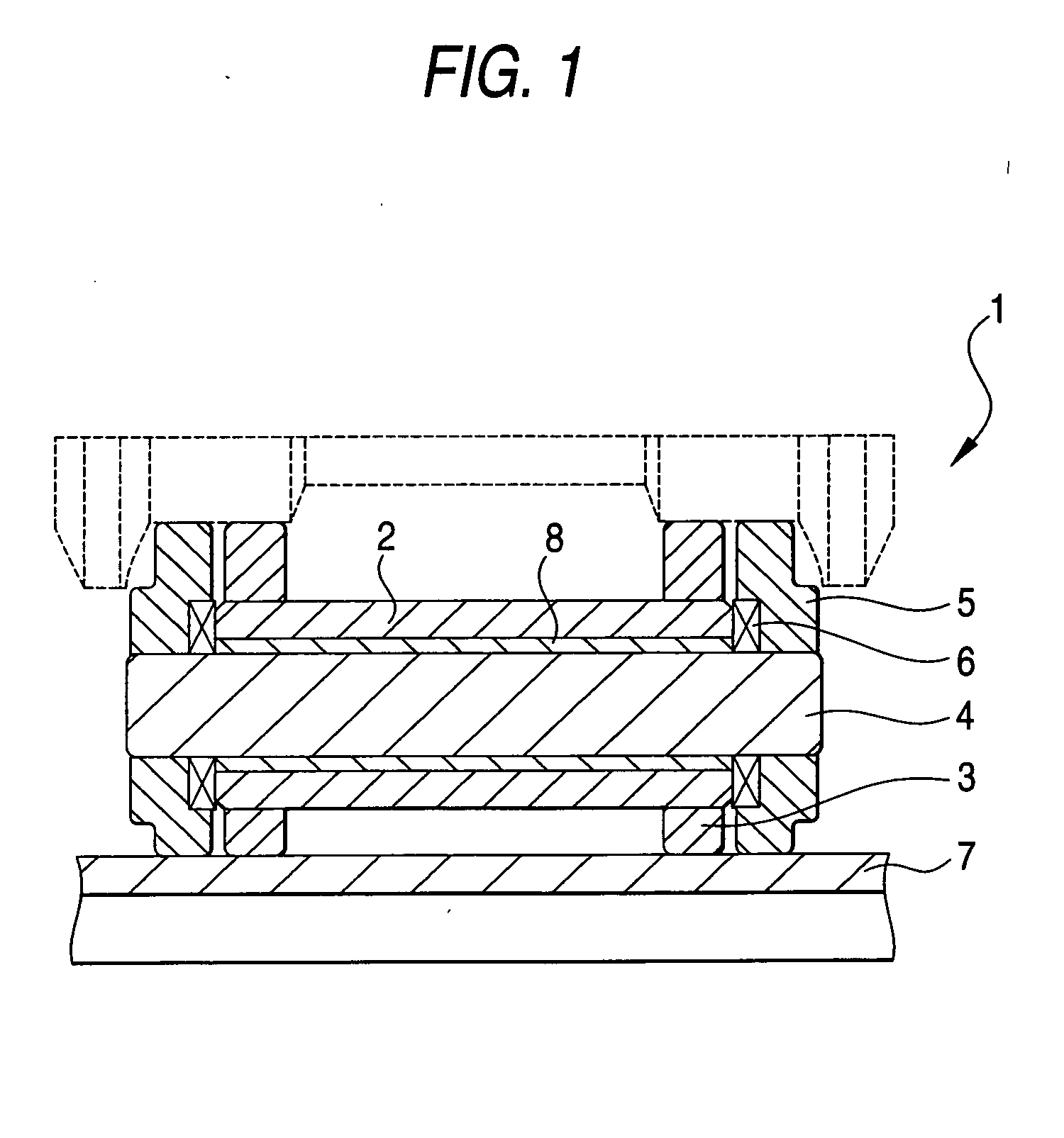
[0105] In this Example, by using a crawler bush having an external diameter of 59.4 mm, an internal diameter of 38.6 mm and a length of 138.5 mm and a crawler pin and by using an impact fatigue testing apparatus shown in FIG. 10, impact fatigue tests were done to examine the influences the clearance between the crawler bush and the crawler pin upon the crawler bush breaking strength and to examine the inserting actions of the metallic sliding member upon the crawler bush breaking strength. Here, the crawler bush was quenched to have a hardened depth of about 3 mm at the HRC45 position by induction-quenching a material SCr440 on both the outer circumference and the inner circumference and was tempered at 180° C. for 3 hrs. On the other hand, the crawler pin was prepared to have a hardened depth of about 4 mm by water-quenching an S45BC material from 850° C. and was tempered at 180° C. for 3 hrs.
[0106] Moreover, the i...
example 2
Manufacture and Sliding Test Results of CuAl Type Sintered Sheet
[0111] By using Al powder, Sn powder, TiH powder, Si powder, Mn powder, Ni powder, phosphor iron powder and electrolytic cathode copper powder (e.g., CE15 of Fukuda Kinzoku) of 300 meshes or less, mixed powders, as enumerated in Table 1, were molded under a molding pressure of 4 tons / cm2 by using a tensile test piece mold of JIS, as shown in FIG. 13. These test pieces were sintered at a degree of vacuum of 0.01 torrs, at 850, 900 and 960° C., for 1 hr by using a vacuum sintering furnace. After this, the test pieces were rolled within an uncracked range and sintered again at the same temperature for 1 hr. The resultant test pieces (of 2S1R material) were measured on their hardness. Moreover, these materials were measured by the constant rate friction wear testing method on the seizure limit values (i.e., PV values) and the wear losses (ΔW, mm) at that time from the bearing pressure, at which the friction coefficient ris...
example 3
Metallic Sliding Material of Oil-Impregnated Structure
[0119] In this Example, the metallic sliding material to be used was examined with a view to improving the seizure resistance under an unbalanced load. In order to evaluate the sliding characteristics of the metallic sliding material, the sliding test piece shown in FIG. 15 was used to evaluate the seizure resistance according to the testing method shown in FIGS. 16A and 16B in terms of the bearing pressure at the instants when the friction coefficient rose seriously, when an unusual noise comes out or when an abnormal wear proceeds.
[0120] Here, the metallic sliding materials used in this Example are enumerated in Table 2 of which No. 1 to No. 5 are sintered sliding materials of Al-bronze type whereas No. 6 and No. 7 are an ingot material and a sintered material of bronze. For comparisons, moreover, examinations were made on the sliding characteristics of the induction-quenched material of S45C.
TABLE 2LimitBearingHard-Pressur...
PUM
 Abstract
Description
Claims
Application Information
 - R&D
- Intellectual Property
- Life Sciences
- Materials
- Tech Scout
- Unparalleled Data Quality
- Higher Quality Content
- 60% Fewer Hallucinations
Browse by: Latest US Patents, China's latest patents, Technical Efficacy Thesaurus, Application Domain, Technology Topic, Popular Technical Reports.
© 2025 PatSnap. All rights reserved.Legal|Privacy policy|Modern Slavery Act Transparency Statement|Sitemap|About US| Contact US: help@patsnap.com


