
Methods and systems for automatically configuring network monitoring system

a network monitoring and automatic configuration technology, applied in the field of network monitoring systems, can solve the problems of manual configuration of the system, unsatisfactory use of external link probes and monitoring units, and the occupying of space in the telecommunications network facilities, etc., and achieve the effect of reducing the amount of labor

Inactive Publication Date: 2007-05-31
TEKELEC GLOBAL INC
View PDF34 Cites 18 Cited by
  • Summary
  • Abstract
  • Description
  • Claims
  • Application Information

AI Technical Summary

Benefits of technology

"The present invention provides a network monitoring system that can automatically adapt to new signaling links and cease monitoring signaling links that are taken out of service, reducing the amount of labor required to reconfigure a network monitoring system. The system includes link interface modules associated with external signaling links and network monitoring applications pre-associated with subsets of the total set of signaling links that could be serviced by the routing node. The network monitoring session is established between the link interface module and the network monitoring application when the link interface module boots up and begins to service a signaling link. The system is completely probeless, meaning there are no additional devices or processes needed to monitor the network."

Problems solved by technology

One disadvantage of using link probes and an external monitoring unit to copy and process signaling messages is that these devices take up space in telecommunications network facilities.
Since these facilities are often located in urban buildings where space expensive, using external link probes and monitoring units may be undesirable.
However, even these hybrid systems required some external link probes to capture all of the signaling messages received by or sent from the routing node being monitored.
One disadvantage of conventional network monitoring systems is that these systems must be manually configured to match the configuration of the routing node being monitored.
Such manual reconfiguration is both time and labor intensive and often results in the network monitoring system being out of sync with the network being monitored.

Method used


Image

  • Methods and systems for automatically configuring network monitoring system
  • Methods and systems for automatically configuring network monitoring system
  • Methods and systems for automatically configuring network monitoring system

Examples


Embodiment Construction

System Overview

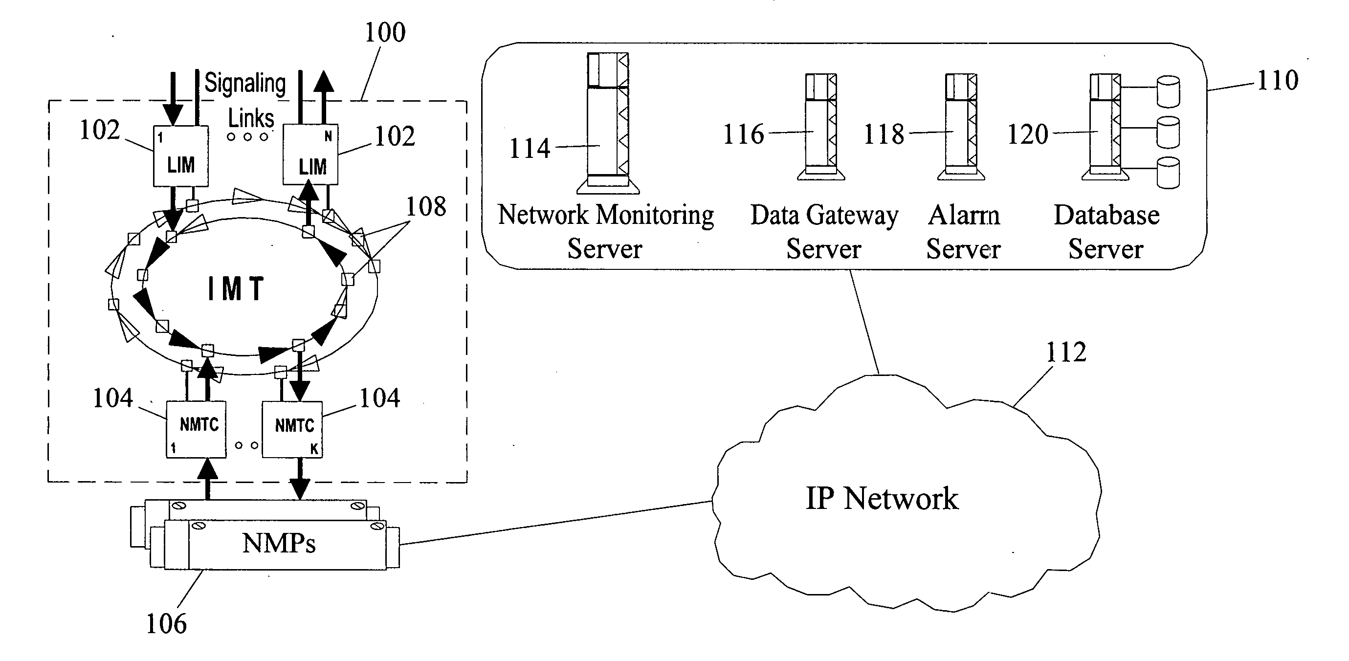
[0037] In one embodiment, an automatically configurable network monitoring system according to the present invention may integrated within a network routing node, such as a signal transfer point or an SS7 / IP gateway. FIG. 1 illustrates an exemplary architecture for an integrated automatically configurable network monitoring system according to an embodiment of the present invention. In FIG. 1, reference numeral 100 represents a routing node, such as an STP or an SS7 / IP gateway. Routing node 100 includes a plurality of link interface modules (LIMs) 102 that send and receive SS7 messages via SS7 signaling links. Although not illustrated in FIG. 1, routing node 100 may also include data communication modules (DCMs) for sending and receiving IP messages via IP signaling links. Network monitoring transport cards (NMTCs) 104 route messages between LIMs 102 and network monitoring processors (NMPs) 106. LIMs 102 and NMTCs 104 are connected via IMT buses 108. NMPs 106 buffer ...


PUM


Abstract

An automatically configurable network monitoring system includes a network monitoring communications protocol used for communications between a network monitoring client executing on a routing node (100) being monitored and a network monitoring server executing on a network monitoring processor (106). According to the network monitoring communications protocol, the network monitoring client broadcasts a network monitoring service request message to the network monitoring servers. The service request message identifies a signaling link for which network monitoring service is being requested. The network monitoring servers provisioned to the requested provide network monitoring service respond affirmatively and thereby automatically grant network monitoring service. The network monitoring system may be completely probeless or, alternatively, used in conjunction with probe-based network monitoring devices.

Description

RELATED APPLICATIONS [0001] This application is a divisional of U.S. patent application Ser. No. 10 / 154,309 filed on May 23, 2002 (pending), the disclosure of which is incorporated herein by reference in its entirety.TECHNICAL FIELD [0002] The present invention relates to network monitoring system. More particularly, the present invention relates to a methods and systems for automatically configuring a network monitoring system. BACKGROUND ART [0003] In telecommunications signaling networks, network monitoring systems are used to perform various functions, such as call tracing, billing, billing verification, fraud detection, protocol verification, etc. In order to perform these functions, network monitoring devices copy signaling messages from signaling links and process these messages into a useful format, such as a transaction record. One conventional method for copying signaling messages is to place link probes on signaling links connected to signaling message routing nodes, such...

Claims


Application Information

Patent Timeline
Patent Type & Authority Applications(United States)
IPC IPC(8): G06F15/173H04L12/56H04L47/32H04W24/00
CPCH04L12/2602H04L41/06H04L41/0806H04L41/0856H04L41/0869H04L41/0886H04L43/00H04L43/06H04L43/062H04L43/0811H04L43/0829H04L43/0882H04L43/10H04L43/106H04L43/12H04L43/16H04L47/12H04L47/32H04W24/00
Inventor LEAN, YOOGINMINNICH, DAVID WAYNESAPP, KEVIN ALLENSPANGLER, RICHARD JAMESTRIMMER, MERL ALLEN JR.
Owner TEKELEC GLOBAL INC
Learn More