
Material and method of capturing oil

Inactive Publication Date: 2007-05-17
BRINK DAMON
View PDF3 Cites 0 Cited by
  • Summary
  • Abstract
  • Description
  • Claims
  • Application Information

AI Technical Summary

Benefits of technology

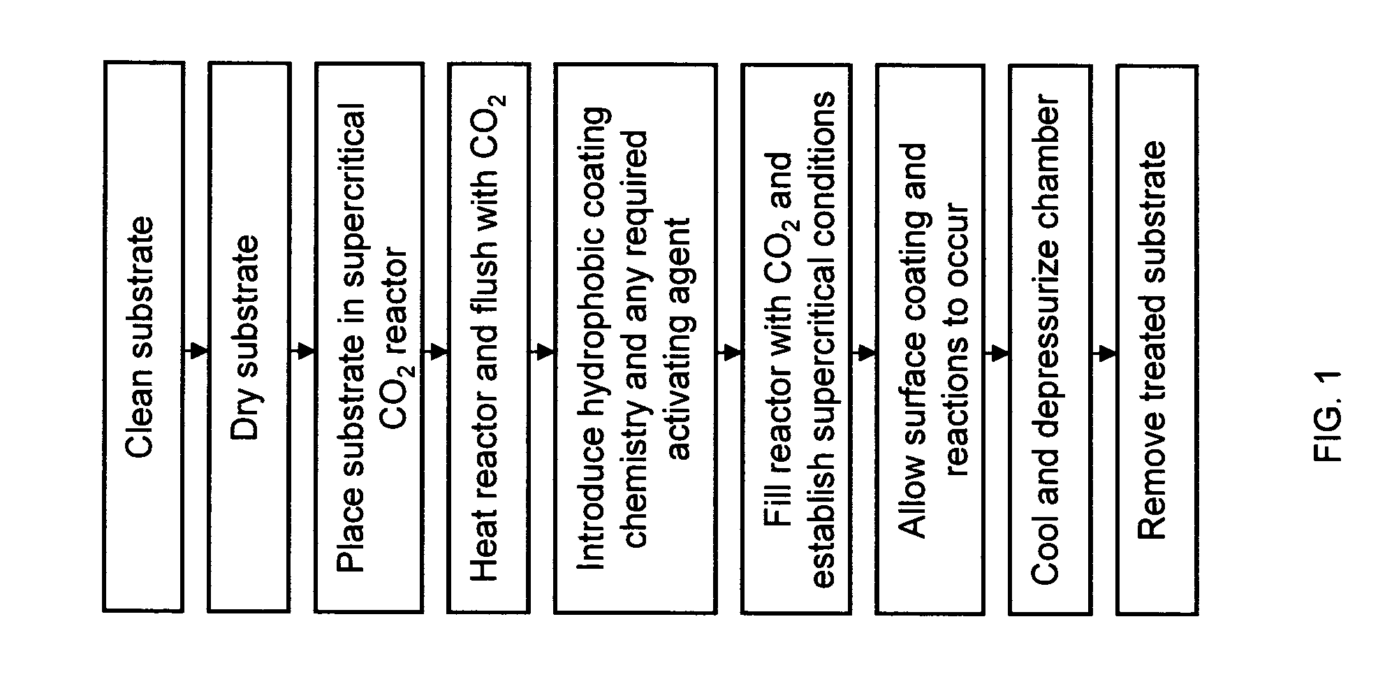
[0007] It is an object of the invention to provide a means for treating many different types of substrates with a hydrophobic coating that will act as an oil-absorbing compound, allowing regionally available, inexpensive substrates to be used.
[0020] The application in certain yet alternate preferred embodiments of the Present Invention of supercritical CO2 deposition allows small structured substrates to be coated, which in turn allows greater oil absorption per weight, coating of inexpensive substrates like sand and diatomaceous earth, and allows them to float on water due to surface tension arguments

Problems solved by technology

Many prior art materials that are used to remove oil from an environment absorb both water and oil, making the process inefficient and the saturated material(s) used heavy with water.
Other prior art approaches create a hydrophobic coating on the surface of oil-retaining particles, but these are particles not easily removed from the surface of the water—without water entrapment—by mechanical means.
Typical prior art coating methodologies do not allow substrates with high porosity to be effectively coated without clogging the pores of the substrates, making the oil-absorbing particles a less-effective sorbant due to decreased effective surface area.
The prior approaches that include making a polymer fiber or particle to absorb the oil from the water can be costly as they do not take advantage of cheap substrate material.

Method used


Image

  • Material and method of capturing oil
  • Material and method of capturing oil

Examples


first preferred embodiment

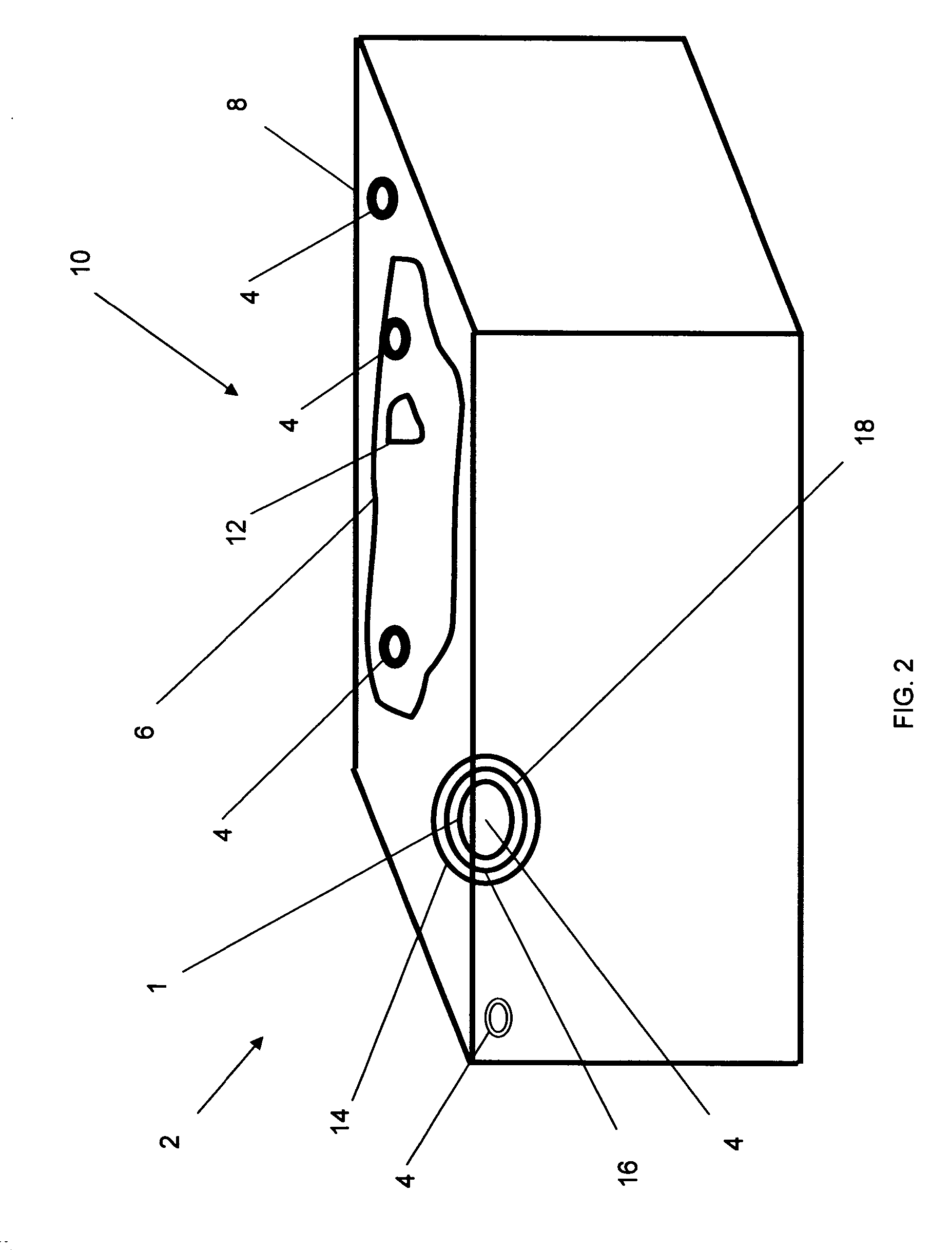
[0027] Referring now generally to the Figures, and particularly to FIG. 2, in a first preferred embodiment of the present invention 2, pristine glass microfibers available from Johns Manville as MicroStrand™ 100 are used as the substrate material 4. One pound of the microfiber material 4 is processed in the present example. The deposition process is scaleable, however, and much larger volumes of microfiber can be processed with a concomitant increase in surface chemistry and reaction chamber size.

[0028] The microfibers 4 are placed directly into the chamber and contained in a perforated stainless steel fixture. No washing is required as the packaging and handling of the fibers is sufficient to keep the substrate clean. The chamber is then sealed and heated to 120° C. to eliminate excess adsorbed moisture from the surface of the fibers. Once this temperature is reached, the chamber is flushed twice with CO2 by pressurizing the chamber to 100 psi and subsequently venting to atmospher...

second preferred embodiment

[0031] In a second preferred embodiment of the present invention, diatomaceous earth is used as the substrate material 4. One pound of the material 4 is processed in the present example. The deposition process is scaleable, however, and much larger volumes of diatomaceous earth can be processed with a concomitant increase in surface chemistry and reaction chamber size.

[0032] The substrate material 4 is washed with water to remove debris and placed into the chamber where it is contained in a perforated stainless steel fixture. The chamber is then sealed and heated to 120° C. to eliminate excess adsorbed moisture from the surface of the material. Once this temperature is reached, the chamber is flushed twice with CO2 by pressurizing the chamber to 100 psi and subsequently venting to atmospheric pressure.

[0033] A small orifice in the top of the pressure vessel is then opened and 15 mL of octylthriethoxy silane (OTS) is metered into the chamber using a pipette. The orifice is then clo...


PUM

PropertyMeasurementUnit
Weightaaaaaaaaaa
Mechanical strengthaaaaaaaaaa
Densityaaaaaaaaaa

Abstract

A material and method useful in absorbing oil is provided. Variations of the material and method are useful in removing an oils spill from the water the oil is contaminating. In the preferred embodiments, a very high density coating is applied to a substrate, preferably using a supercritical coating process. The coating may approximate a Self-Assembled-Monolayer in the best case.

Description

RELATED APPLICATIONS [0001] This application claims priority to U.S. Provisional Application, Ser. No. 60 / 737,906, filed Nov. 17, 2005FIELD OF THE INVENTION [0002] The Present Invention generally relates to materials and techniques used to absorb oils. And particularly to materials and techniques used to remove oils from environments. BACKGROUND OF THE INVENTION [0003] Many prior art materials that are used to remove oil from an environment absorb both water and oil, making the process inefficient and the saturated material(s) used heavy with water. There are multiple prior art approaches to the problem, to include: a, mechanical containment and separation; b. dispersion and decomposition of oil; c. filtration of oil; and d. absorption of oil by substrate which will subsequently be removed. [0004] In the prior art of oil absorption, specific prior art coatings have been used to attempt to create a hydrophobic surface which will therefore selectively adhere to a surface. Other prior ...

Claims


Application Information

Patent Timeline
IPC IPC(8): B32B5/02
CPCB82Y30/00C09D5/00Y10T442/20Y02P20/54
Inventor BRINK, DAMON
Owner BRINK DAMON
Learn More