
Plasma containment method

a technology of plasma and containment method, which is applied in the direction of nuclear reactors, nuclear energy reduction, etc., can solve the problems of prohibitively complex and/or expensive operation of large devices and various supporting components in widespread applications, and achieve the effect of enhancing stability and ensuring the stability of plasma

Inactive Publication Date: 2007-05-03
EDWARDS W FARRELL +1
View PDF15 Cites 8 Cited by
  • Summary
  • Abstract
  • Description
  • Claims
  • Application Information

AI Technical Summary

Benefits of technology

[0008] The foregoing drawbacks can be overcome by a containment method that enhances stability. Such a plasma can be designed and operated by determining a stable energy state of the system without imposing a quasi-neutrality condition; a contained plasma that includes a substantial induced electrostatic field will contribute significantly to the stability of the plasma. Compact devices based on such contained plasmas can be used in different applications, such as a neutron generator, an x-ray generator, and a power generator.

Problems solved by technology

Consequently, such large devices and various supporting components can be prohibitively complex and / or expensive to operate in widespread applications.

Method used


Image

  • Plasma containment method
  • Plasma containment method
  • Plasma containment method

Examples


Embodiment Construction

[0036] The present teachings generally relate to systems and methods of plasma confinement at a relatively stable equilibrium. In one aspect, such a plasma includes a substantial internal electrostatic field that facilitates the stability and confinement of the plasma.

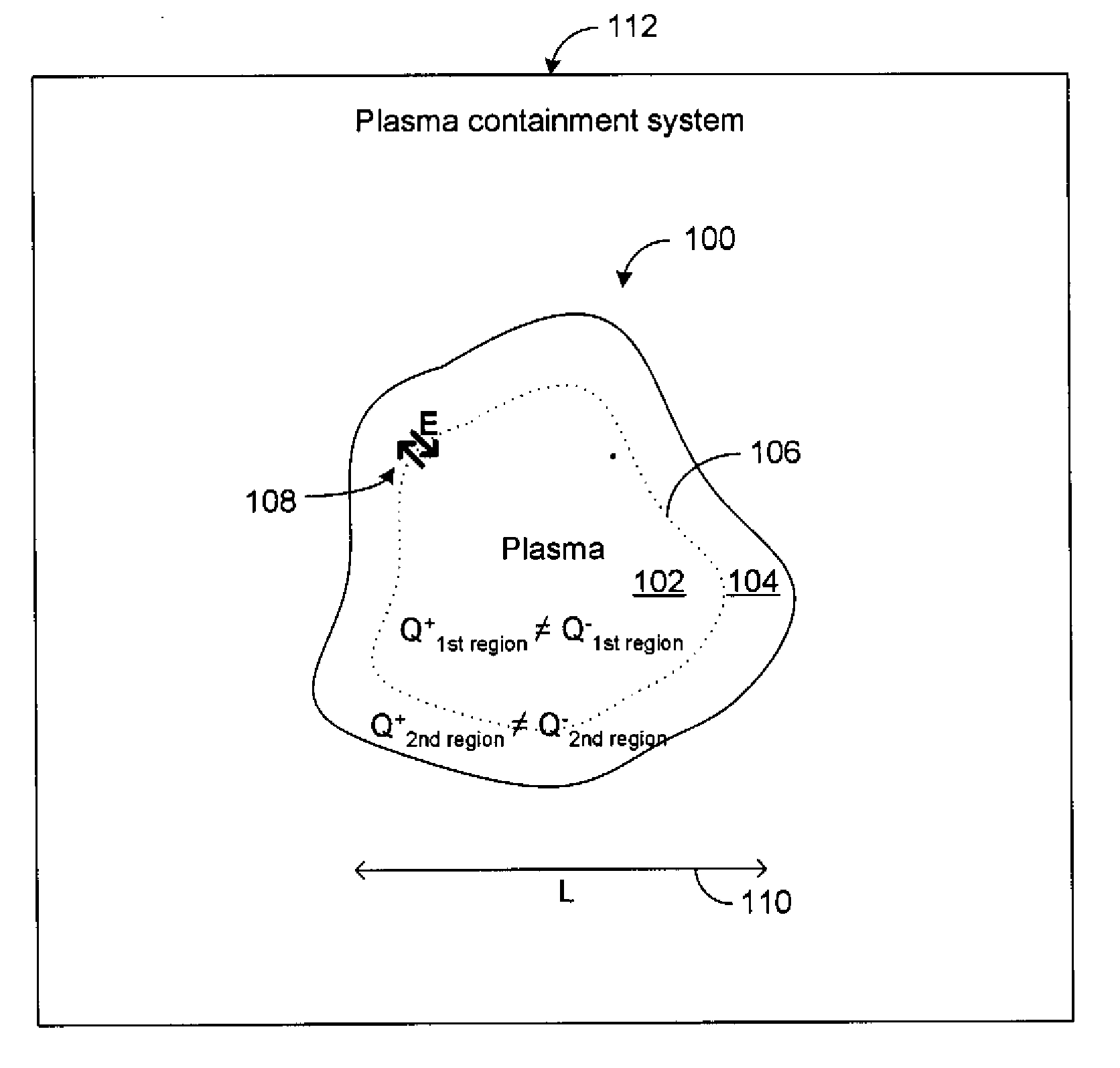
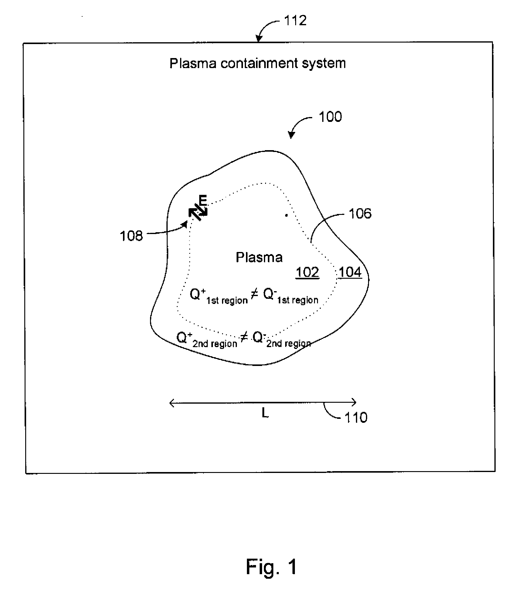
[0037]FIG. 1 shows a confined plasma 100 confined by a containment system 112. The plasma 100 defines a first region 102 substantially bounded by a boundary 106, and a second region 104 substantially bounded by the internal boundary 106 and the plasma's boundary. The plasma 100 has at least one dimension on the order of L as indicated by an arrow 110.

[0038] For the purpose of description, the plasma 100 can be characterized as a two-fluid system having an electron fluid and an ion fluid. It will be understood that the ion fluid can involve ions based on the same or different elements and / or isotopes. It will also be understood that the collective fluid-equation of characterization of the plasma herein is simply one w...


PUM


Abstract

A method for plasma containment is disclosed comprising varying the system energy subject to Maxwell's equations, momentum moment equations, and adiabatic equations of state, without imposing a quasi-neutrality condition. In one embodiment, electrons are confined by magnetic forces and ions by internal, electrostatic forces that arise due to charge separation of the two fluids. In one embodiment, input parameters for the energy variation process are selected so as to satisfy a plasma beta parameter condition, thereby reducing the number of control variables by one. The radial scale length for cylindrically symmetric plasmas in one-dimensional equilibrium is characterized by the electron skin depth. Such plasmas can be confined as a high aspect ratio toroid having compact dimensions. Applications of the invention include neutron generation, x-ray generation, and power generation.

Description

PRIORITY APPLICATIONS [0001] This application is a divisional of U.S. patent application Ser. No. 10 / 804,520, filed 19 Mar. 2004, titled “Systems and Methods of Plasma Containment,” incorporated herein by reference. Application Ser. No. 10 / 804,520, in turn, claims priority benefit of U.S. provisional patent application No. 60 / 456,832, filed 21 Mar. 2003, titled “A Method of Obtaining Design Parameters for a Compact Thermonuclear Fusion Device,” incorporated herein by reference.BACKGROUND [0002] 1. Field [0003] The present teachings generally relate to the field of plasma containment and more particularly, to systems and methods for establishing a stable plasma in a relatively compact containment chamber. [0004] 2. Description of the Related Art [0005] Nuclear fusion occurs when two relatively low mass nuclei fuse to yield a larger mass nucleus and reaction products. Because a substantial amount of energy is associated with the reaction products, controlled nuclear fusion research is...

Claims


Application Information

Patent Timeline
IPC IPC(8): G21B1/00G21B1/05H05G2/00H05H1/02H05H3/06
CPCG21B1/05H05G2/003H05H1/02H05H3/06Y02E30/126Y02E30/10
Inventor EDWARDS, W. FARRELLHELD, ERIC D.
Owner EDWARDS W FARRELL
Learn More