
Electrophysiology/ablation catheter and remote actuator therefor

a technology of electrophysiology and catheter, applied in the field of catheter, can solve the problems of difficult monitoring of cardiac signals contaminated with such “noise”, significant level of electrical “noise” generated, and relatively high cost of catheters of this type, so as to reduce the compression load of the inner guide tube, reduce the cost of catheter construction, and reduce the effect of insertion and removal

Inactive Publication Date: 2007-04-05
ST JUDE MEDICAL ATRIAL FIBRILLATION DIV
View PDF54 Cites 39 Cited by
  • Summary
  • Abstract
  • Description
  • Claims
  • Application Information

AI Technical Summary

Benefits of technology

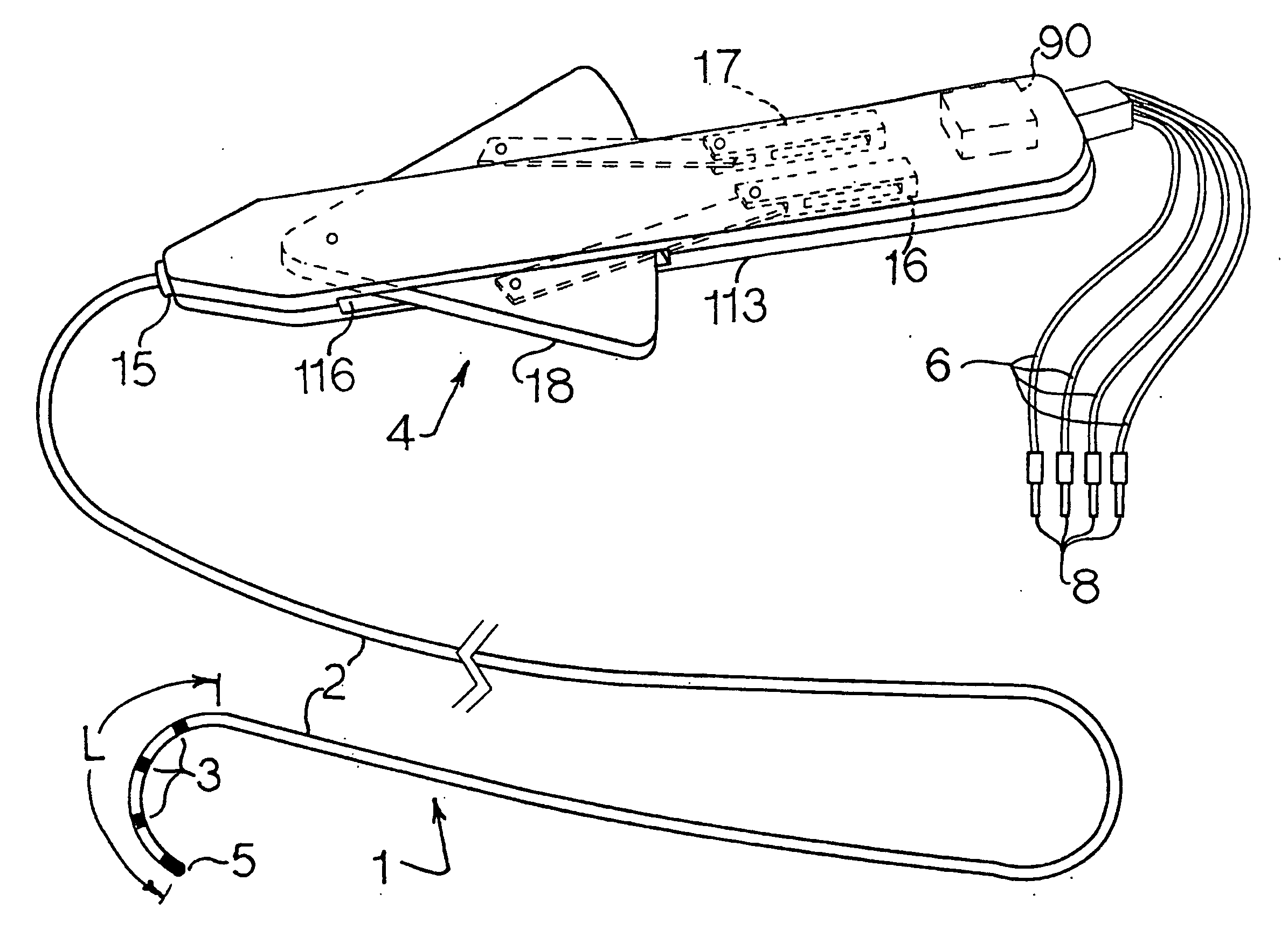
[0035] A further objective of this invention is to provide an electrophysiology catheter having a disposable blood contacting portion comprising the catheter main body and electrodes with a deflectable distal segment. A re-useable portion comprising the actuator handle with its associated tip deflecting mechanism which is easily attachable / detachable from the blood contacting portion.
[0051] The present invention utilizes a novel catheter construction which eliminates the compression loading of the inner guide tube and provides design flexibility and economies in construction.

Problems solved by technology

This known ablation procedure, using a self-adhesive patch as the return path of electrical energy to the energy source, may result in a significant level of electrical “noise” that is generated by the energy source during the energy delivery period.
Cardiac signals contaminated with such “noise” have been found difficult to monitor during energy delivery period.
Catheters of this type are relatively expensive.
The catheter price and the convention of its “one-time-use-only” have an impact on the overall cost of cardiac electrophysiology and ablation procedures.
The above desirable performance features for the catheters with deflectable distal portion have not been met by known commercially available catheters.
The catheters of the prior art referenced in this document have not satisfied all of the desirable performance features mentioned above.
For example, in the aforesaid U.S. Pat. No. 4,960,134, issued to Webster Jr., the sliding pull wire arrangement does not satisfy the low force requirement on the manual actuator of the catheter handle for formation of curvature at the catheter distal portion.
The cardiac catheters of the prior art are not only expensive but are solely for “one-time-use-only”.
The catheter price and the convention of “one-time-use-only” increases the overall cost of electrophysiology and ablation procedures.
Presently employed known methods of cardiac ablation procedure and presently employed known ablation catheters have the disadvantage of requiring an electrically conductive patch on the patient skin during the procedure.

Method used


Image

  • Electrophysiology/ablation catheter and remote actuator therefor
  • Electrophysiology/ablation catheter and remote actuator therefor
  • Electrophysiology/ablation catheter and remote actuator therefor

Examples


embodiment 4

[0140] Referring to FIGS. 9, 10, 11, 12, and 13 an alternative embodiment 4′ of the catheter handle is shown with a cam-follower type pull / push mechanism for affecting formation of curvature at the distal portion of the catheter upon movement of actuator 128. The pivoted delta shaped actuator 128 is disposed to pivot freely about pin 43 within the handle 113′.

[0141] Referring to FIG. 10, the mechanism of handle 4′ comprises two symmetrically coupled followers 40 and 41 disposed for sliding movement on block 113′ and with a single rotating cam 42 as the driver. The cam 42 is rigidly attached to the apex of the delta-shaped actuator 128 for rotation therewith. The center 44 of cam 42 is pivoted within the catheter handle body 113′ about a pin 43.

[0142] The two sliding followers 40 and 41 are driven by cam 42. Each of the sliding followers 40 and 41 includes an adjusting screw 45 and 46 respectively. The tip of each of these adjusting screws 45, 46 are anchored to the cam profile and ...

embodiment 154

[0159] The second sub-system 61 of the embodiment 154 comprises the front or left hand portion of the catheter handle end and includes:

[0160] a cylindrical housing 73;

[0161] a manual back-up actuator 74 in the form of a tubular member disposed concentrically over housing 73;

[0162] a motor control switch 75;

[0163] the multi connector junction jack 69 is disposed inside the right hand end of the cylindrical housing 73;

[0164] a connecting rod or pin 76 interconnects manual drive actuator 74 to core 72 through a slot 82 formed in housing 73;

[0165] a front bearing support 77 is disposed in housing 73 adjacent the left end thereof;

[0166] a rear bearing support 78 is disposed in housing 73 adjacent the right hand end thereof; and,

[0167] an angular displacement sensor 79 is disposed in housing 73 and located at the right hand end thereof for sensing rotation of core 72 with respect to housing 73 of sub-system 61.

[0168] The core 72 of sub-system 61 includes two identical pull / push me...

embodiment 170

[0178] The embodiment 170 includes an additional annular reference electrode 103 on the catheter main exterior tube 2 for a uni-polar application of the catheter during intra-cardiac mapping procedures. In addition, the catheter 170 may include a blood-clot sensor or detector (not shown) and a temperature indicator (not shown) in the catheter handle 4. The purpose of blood clot sensor is to stop or reduce the delivery of electrical energy to the heating element during ablation procedures.

[0179] Referring to FIGS. 20a through 20d a further embodiment 180 of the catheter of the present invention is illustrated and has the feature that the blood contacting portions are disposable; and, thus, the embodiment 180 is particularly suitable for cardiac electrophysiology / ablation procedures. The embodiment 180 is a modified version of the catheter presented in FIG. 1 of this invention. The modification is applied in two parts. The first modification pertains to the shape of the distal tip ele...


PUM


Abstract

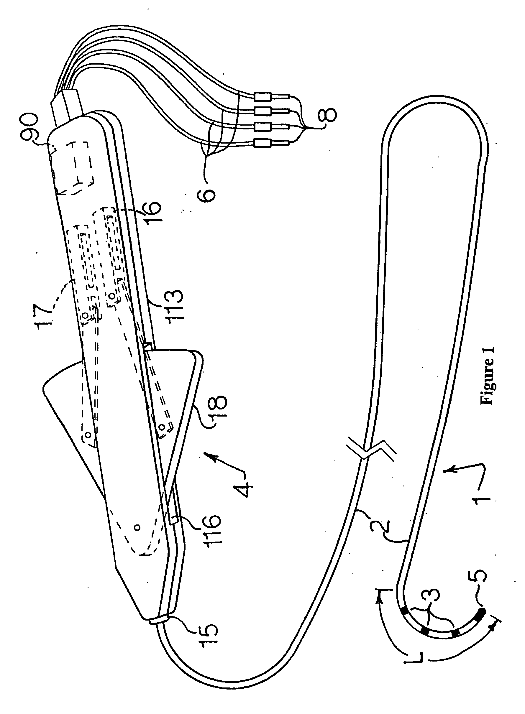
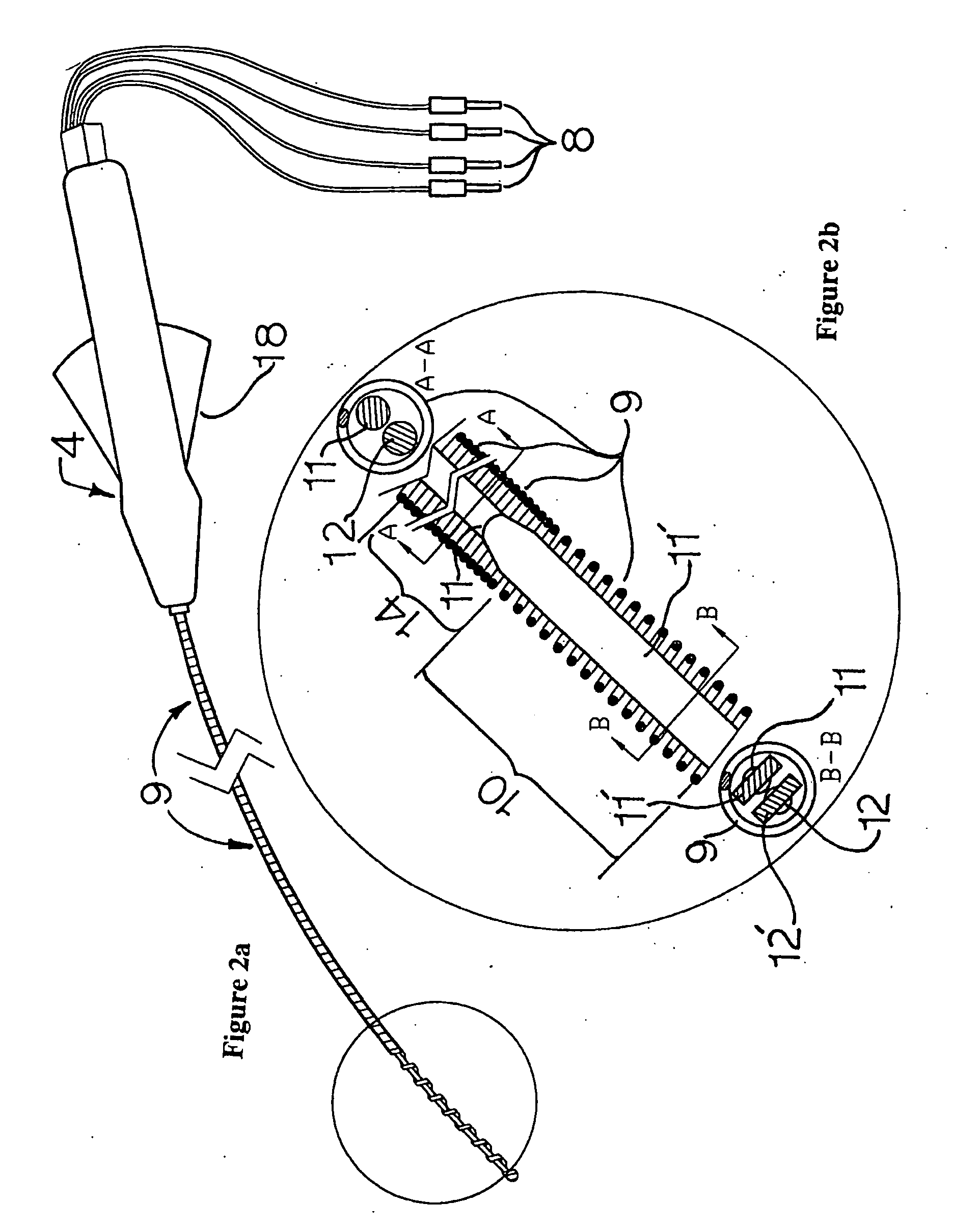
A cardiac catheter for minimally invasive diagnostic and / or ablation procedures includes an elongated cylindrical, electrically non-conductive exterior tube with surface electrodes disposed on its distal portion and a handle on its proximal end. The distal portion can be curved into a curvature retained by a single action on a manual actuator. An electromechanical drive system may be incorporated into the handle. An electrical heating element may be incorporated within the distal electrode for ablation procedures. A removable, disposable blood contacting segment may be provided. The non-blood contacting actuator is thus reusable. The catheter includes two tension / compression members, which are wires with circular cross-sections that are integrally formed into ribbon-like configurations at their distal portions, for curvature formation. The handle includes a pivoted member movable in one direction by the thumb of the user's hand grasping the handle and in the opposite direction by the other fingers of the same hand.

Description

CROSS-REFERENCE TO RELATED APPLICATIONS [0001] This application is a continuation of U.S. application Ser. No. 10 / 260,242, filed 30 Sep. 2002, now pending (the '242 application), which is a divisional of U.S. application Ser. No. 09 / 232,866, filed 15 Jan. 1999, now abandoned (the '866 application), which is a continuation-in-part of U.S. application Ser. No. 08 / 880,080, filed 20 Jun. 1997, now U.S. Pat. No. 5,861,024 (the '080 application). The '242 application, the '866 application, and the '080 application are hereby expressly incorporated by reference in their entirety as though fully set forth herein.BACKGROUND OF THE INVENTION [0002] a. Field of the Invention [0003] The present invention relates to a catheter employed for diagnostic and / or therapeutic procedures in medicine, more specifically in minimally invasive cardiac electrophysiology studies and / or cardiac ablation procedures. [0004] b. Description of the Prior Art [0005] The primary device for an intra-cardiac electrophy...

Claims


Application Information

Patent Timeline
Patent Type & Authority Applications(United States)
IPC IPC(8): A61B18/18A61B18/14A61N1/05
CPCA61B18/1492A61B2017/003A61B2018/00839A61N1/0565
Inventor RASHIDI, RASSOLL
Owner ST JUDE MEDICAL ATRIAL FIBRILLATION DIV
Learn More