Fuel cell

a fuel cell and catalyst technology, applied in cell components, electrochemical generators, fused electrolyte fuel cells, etc., can solve the problem of insufficient co resistance at the anode, and achieve the effect of improving the characteristics of fuel cells and enhancing the co resistance of catalysts

Inactive Publication Date: 2007-04-05
SANYO ELECTRIC CO LTD
View PDF3 Cites 5 Cited by
  • Summary
  • Abstract
  • Description
  • Claims
  • Application Information

AI Technical Summary

Benefits of technology

[0007] The present invention has been developed in view of the foregoing problems. It is thus a general purpose of the present invention to provide a technology that enhances the CO resistance of a catalyst to thereby improve the characteristics of fuel cells.
[0011] In the present invention, by employing the above configuration, even when CO sticks to the first catalyst material, a state in which CO is easily converted to CO2 is maintained by means of the second catalyst material. Therefore, by supplying oxygen (O) from the oxygen-supplying material, the reduction in the ability of the first catalyst material caused by CO poisoning can be suppressed (and CO resistance is therefore improved) to thereby improve the voltage characteristics of the fuel cell.
[0012] Furthermore, another embodiment of the present invention relates to a catalyst employed in a fuel cell. The catalyst includes a first catalyst material having a function of extracting an electron from a reaction fluid, a second catalyst material having a function of reducing activation energy for conversion of carbon monoxide to carbon dioxide, and an oxygen-supplying material which supplies oxygen. According to this catalyst for a fuel cell, even when CO sticks to the first catalyst material, a state in which CO is easily converted to CO2 is maintained by means of the second catalyst material. Therefore, by supplying oxygen (O) from the oxygen-supplying material, CO resistance can be improved, whereby the durability of a fuel cell employing this catalyst can also be improved.
[0014] The gold particles having the peak of the particle diameter distribution within the range of from 1 nm to 5 nm, or so-called gold nanoparticles, exhibit outstanding CO oxidizing ability. Furthermore, the CO oxidizing ability of the gold nanoparticles can be enhanced by employing, as a material supporting the gold nanoparticles, a transition metal selected from group 3 to group 11, particularly a transition metal having an oxidation-reduction potential within a range in which a standard electrode potential thereof with respect to a standard hydrogen electrode is −0.25 V or more and 0.25 V or less.
[0017] The relative concentration of carbon monoxide contained in the reaction fluid is higher in a region close to a discharging portion from which a reaction fluid not reacted at the first electrode is discharged than in a region close to an introduction portion for supplying the reaction fluid to the first electrode. Therefore, in the region contacting a fluid having higher relative carbon monoxide concentration (the second region), Co can be effectively converted to CO2 by increasing the concentration of the second catalyst material or the concentration of the oxygen-supplying material so as to increase the number of reaction sites where CO is brought into close proximity of 0.

Problems solved by technology

However, since carbon monoxide (CO) generated during the processes represented by the chemical equations (1) and (2) cannot be fully eliminated, CO in an amount of several ppm to several tens of ppm enters the anode of the fuel cell.
However, this technology is still in the research stage.
Although fuel cells appear on the verge of becoming genuinely widespread, it has been found that, at present, the CO resistance at the anode is not sufficient.

Method used


Image

  • Fuel cell
  • Fuel cell
  • Fuel cell

Examples


first embodiment

[0032] [First Embodiment]

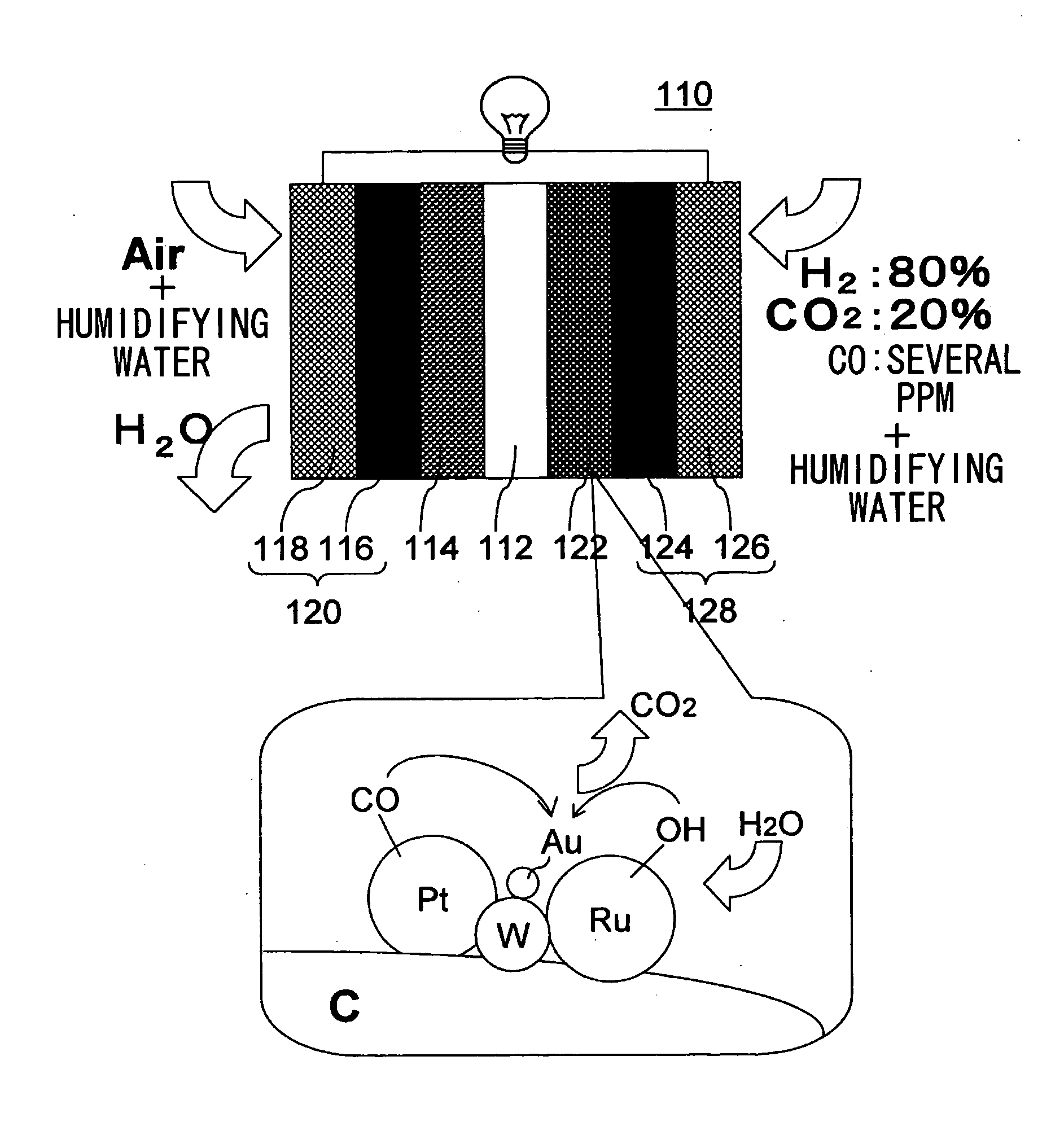
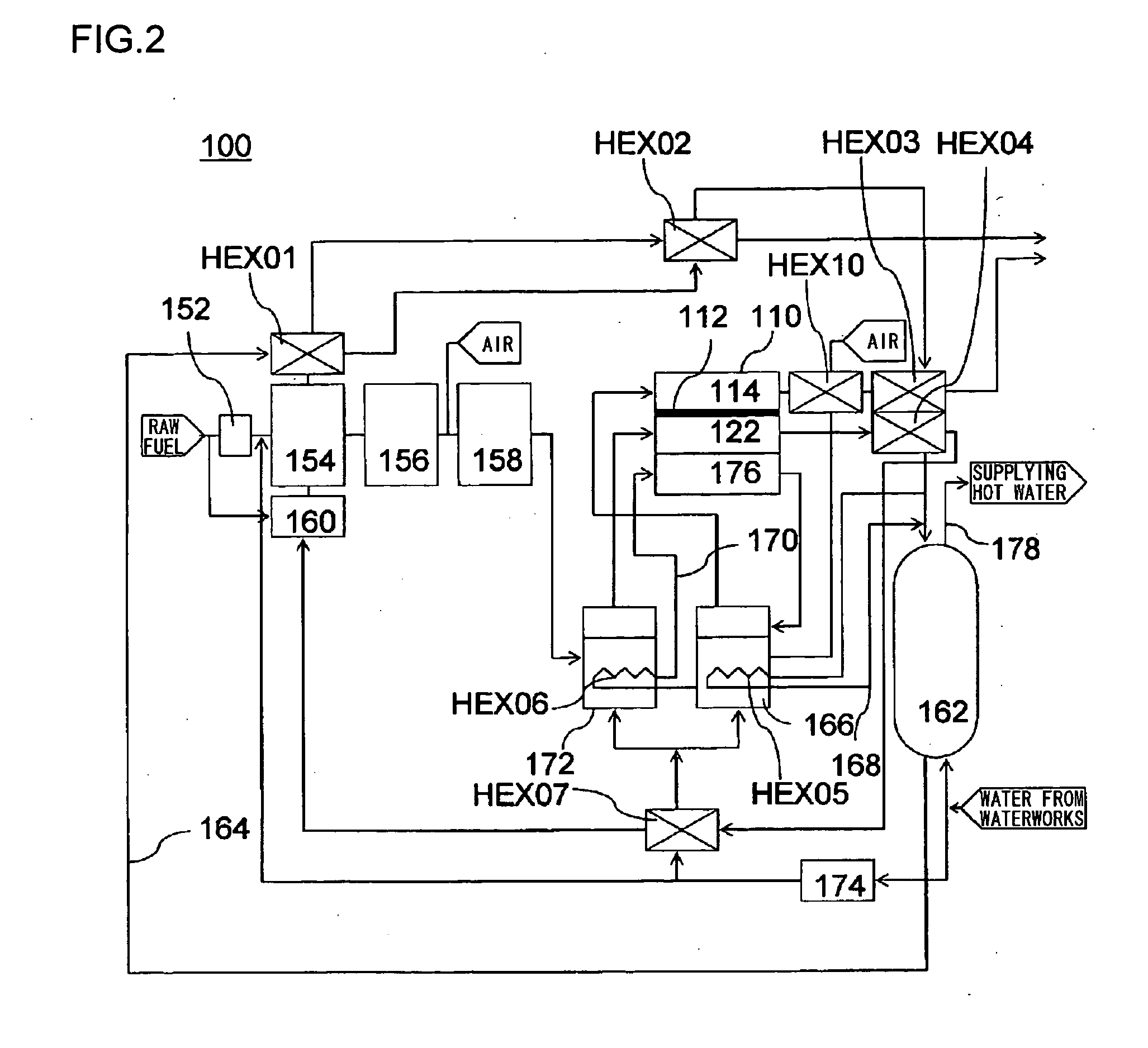
[0033] In this embodiment, with reference to FIG. 2, a description will be given of a fuel cell 110 employed in a domestic-use fuel cell co-generation system 100. The domestic-use fuel cell co-generation system 100 includes: a reforming apparatus which reforms raw fuel (hydrocarbon-based fuel) such as LPG or city gas and generates reformed gas containing hydrogen (fuel) in an amount of about 80%; a fuel cell 110 which generates electrical power using the reformed gas supplied from the reforming apparatus and oxygen (oxidant) in air; and a hot water storage apparatus which recovers and stores heat generated in the reforming apparatus and the fuel cell 110 in the form of hot water (water of 40° C. or higher). Thus, this system has both a power generation function and a hot water supplying function.

[0034] Normally, as safety measures in case of a gas leak, an odor is added, by use of a sulfide, to the raw fuel, such as LPG or city gas, supplied to homes. Howev...

second embodiment

[0056] [Second Embodiment]

[0057] In this embodiment, with reference to FIG. 6, a description will be given of a fuel cell 210 employed in a mobile-use fuel cell system 200. The fuel cell 210 is a direct methanol fuel cell (DMFC) in which an aqueous solution of methanol or pure methanol (hereinafter referred to as “methanol fuel”) is supplied to anodes 222 (222a, 222b, and 222c). The fuel cell 210 includes a catalyst coated membrane (CCM) 230 serving as a power generation unit and which is formed by sandwiching a solid polymer membrane 212 between cathodes 214 (214a, 214b, and 214c) and the anodes 222 without using a diffusion layer.

[0058] The methanol fuel to be supplied to the anodes 222 is supplied to a fuel chamber 254 from outside of the fuel cell 210 through a methanol fuel supply hole (not shown). The methanol stored in the fuel chamber 254 is supplied to each of the anodes 222. At the anodes 222, the reaction of methanol occurs as indicated in the chemical equation (3). Furt...


PUM

PropertyMeasurementUnit
particle diameter distributionaaaaaaaaaa
oxidation-reduction potentialaaaaaaaaaa

Abstract

A fuel cell is provided which can enhance the CO resistance to thereby improve the voltage characteristics thereof. A fuel cell includes an electrolyte layer, a first electrode provided on one surface of the electrolyte layer, and a second electrode provided on the other surface of the electrolyte layer. In this fuel cell, a reaction fluid to be supplied to the first electrode contains carbon monoxide or carbon monoxide is generated from a reaction fluid having been supplied to the first electrode. The first electrode of the fuel cell includes a first catalyst material (Pt) having a function of extracting an electron from the reaction fluid, a second catalyst material (WAu) having a function of reducing the activation energy for conversion of carbon monoxide to carbon dioxide, and an oxygen-supplying material (Ru) supplying oxygen.

Description

BACKGROUND OF THE INVENTION 1. Field of the Invention [0001] The present invention relates to a fuel cell, and in particular, to a fuel cell having high CO resistance. 2. Description of the Related Art [0002] In this age, the new technologies that have evolved, such as IT and biotechnology, have had a global impact. Even in such circumstances, however, the energy industry remains one of the largest basic industries. In recent years, as environmental awareness including prevention of global warming has grown, expectations regarding the introduction of a so-called new energy have increased. This new energy has advantages in terms of reduction in power transmission losses and security of power supply, in addition to environmental friendliness, given that the energy can be produced in dispersed sites close to the electrical power consumers. Furthermore, as a secondary effect, it is expected that new related industries will be created through the development of this new energy. Efforts t...

Claims


Application Information

Patent Timeline
Patent Type & Authority Applications(United States)
IPC IPC(8): H01M8/06H01M4/90H01M4/92
CPCB82Y30/00H01M4/8621H01M4/8652H01M4/90H01M4/921H01M8/04007H01M8/04291H01M8/0618H01M8/0662H01M8/0675H01M2004/8684H01M2008/1095H01M2250/405Y02E60/50Y02B90/16Y02E60/523Y02B90/10H01M8/02
Inventor MATSUOKA, KOJIIKOMA, YOSHIHIRO
Owner SANYO ELECTRIC CO LTD
Why Eureka
Try Eureka