Cable or the like protection and guide device

a technology of protection and guide device and cable, which is applied in the direction of machine supports, manufacturing tools, couplings, etc., can solve the problems of easy vibration disengagement, serious failure of engagement, and difficulty in adjusting the position of the opening/closing arm, so as to reduce the effort of operation, the device is excellent endurance, and the operation is reliable.

Active Publication Date: 2007-03-29
TSUBAKIMOTO CHAIN CO
View PDF4 Cites 12 Cited by
  • Summary
  • Abstract
  • Description
  • Claims
  • Application Information

AI Technical Summary

Benefits of technology

[0015] The cable or the like protection and guide device of the invention includes a main locking mechanism which disengageably secures the opening/closing arm and the other link plate. An auxiliary locking mechanism also disengageably locks the opening/closing arm and the other link plate. The engagement between the opening/closing arm and the other link plate is performed by dual locking engagement mechanisms. A load, which acts on the opening/closing arm is distributed between both the main locking mechanism and the auxiliary locking mechanism. Excellent endurance of the device can be achieved. Additionally, even if the main locking mechanism is disengaged during operation the auxiliary mechanism is still engaged and inadvertent disengagement of the opening/closing arm during operation is avoided. As a result, reliable engagement and disengagement of the opening/closing arm can be realized. Additionally, the following peculiar effects can be obtained.
[0016] The main locking mechanism comprises an engagement pin and an engagement piece. The engagement pin is integrally molded in an upper portion of the other link plate and extends in the longitudinal direction of the chain. The engagement piece is slidably attached to the second end of the opening/closing arm and is movable from the outside toward the inside of the link plate along the opening/closing arm. The engagement piece when opened reveals an engagement pin insertion groove engageable with the engagement pin. The engagement piece moves in the direction of the opening/closing arm. The pivoting direction of the opening/closing arm and the direction of movement of the engagement piece are different from each other. Thus, as long as the engagement piece has engaged the engagement pin and the protrusion piece is inserted into the protrusion piece insertion groove, the opening/closing arm is not inadvertently disengaged from the link plate. Further, since the engagement pin insertion groove in the engagement piece is moved from the outside toward the inside of the link plate to engage with an engagement pin, the engagement operation for engagement securing the opening/closing arm to the link plate becomes easy and the efforts of operation can be reduced.
[0017] The auxiliary locking mechanism comprises a protrusion piece insertion groove and an auxiliary protrusion piece. The protrusion piece insertion groove is integrally molded in the other link plate and in the vicinity of an end portion of the engagement pin. The opening of the protrusion piece insertion groove faces the inside of the link plate. An auxiliary protrusion piece is integrally molded on the second end

Problems solved by technology

As a result when both elements are not reliably fixed to a required engagement position due to insufficient positioning there are problems.
One serious problem that may occur is the easy disengagement by vibration or the like during operation.
This can lead to a serious failure in engagement.
Further, when members forming the engagement structure break, the other end of the opening/closing arm cannot be fixed to the upper end portion of the other link plate and the opening/closing arm is separated.
Further, when an upper end portion of the other link plate and the ot

Method used


Image

  • Cable or the like protection and guide device
  • Cable or the like protection and guide device
  • Cable or the like protection and guide device

Examples


example

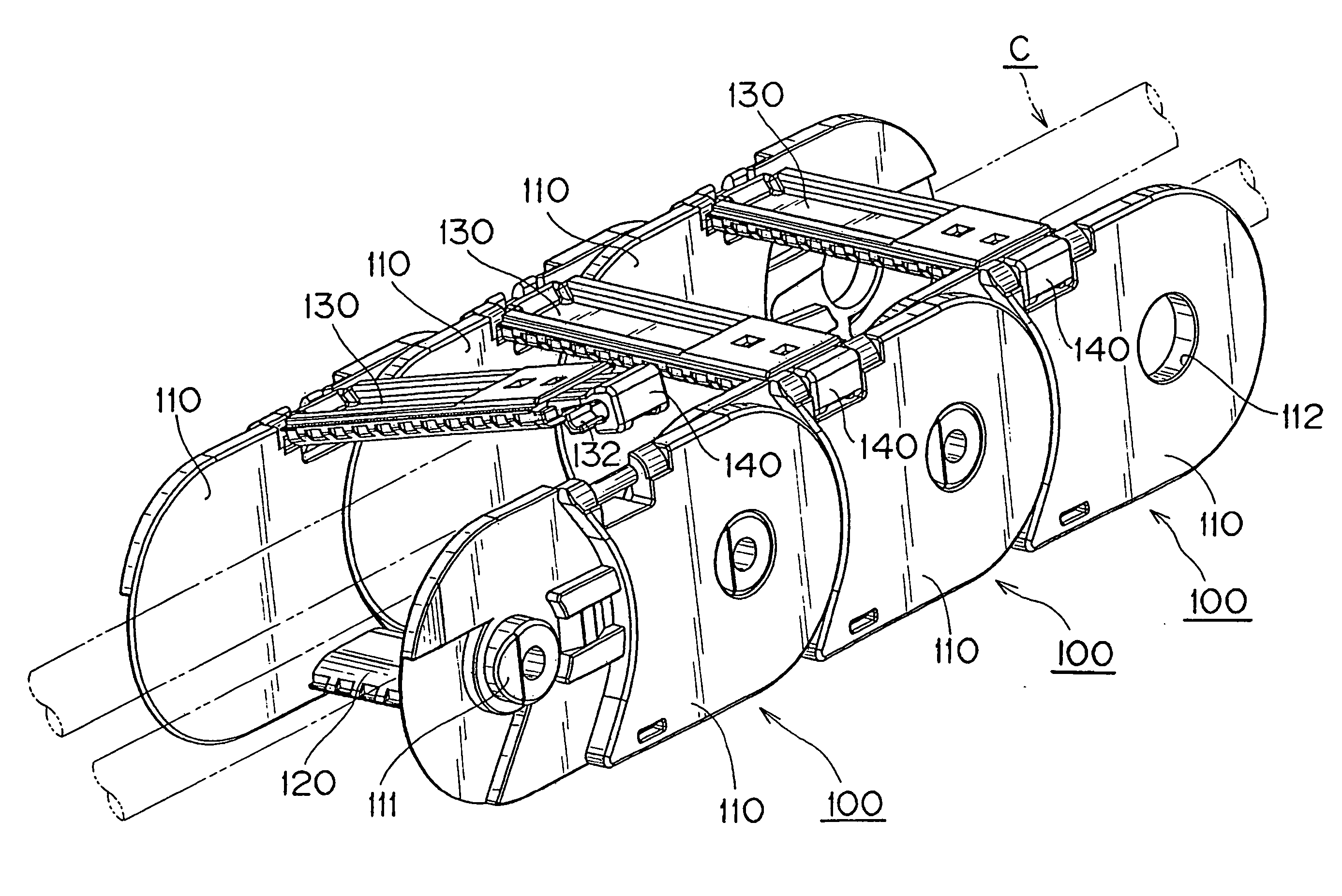
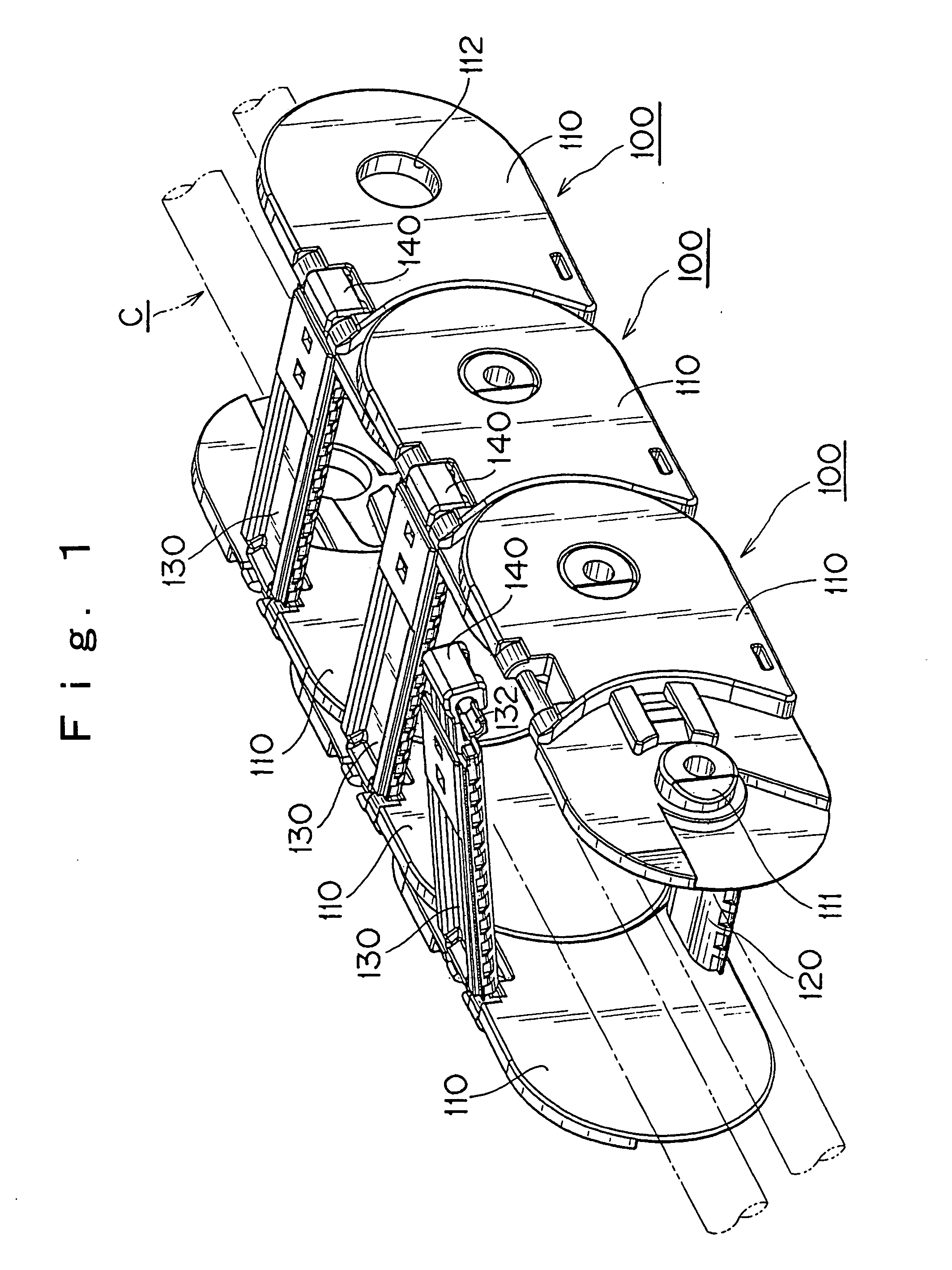
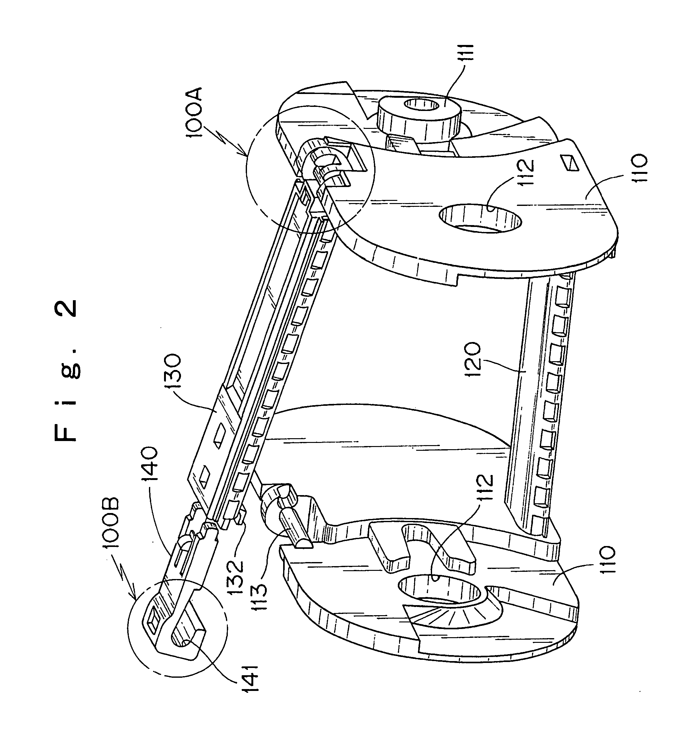
[0035] A cable or the like protection and guide device, which is one example of the present invention, will be described with reference to drawings.

[0036] First, FIG. 1 is a schematic view of a cable or the like protection and guide device, which is one example of the present invention. FIG. 2 is an entire view of a link body shown in FIG. 1. FIG. 3 is a perspective view showing a connection state between link plates and a connecting arm. FIG. 4 is an exploded view of an opening / closing arm and an engagement piece. FIG. 5 is a perspective view showing a state where an opening / closing arm is locked by only an auxiliary locking mechanism. FIG. 6 is an enlarged perspective view showing a securing starting state of a main locking mechanism. FIG. 7 is an enlarged perspective view showing a securing completion state of the main locking mechanism. FIG. 8 is an enlarged perspective view showing a locking starting state of an auxiliary locking mechanism. FIG. 9 is an enlarged perspective vi...


PUM

PropertyMeasurementUnit
Electric chargeaaaaaaaaaa
Currentaaaaaaaaaa
Digital informationaaaaaaaaaa

Abstract

The object of the instant invention is to provide a cable (or the like) protection and guide device in which inadvertent disengagement during operation can be avoided. Engagement between an opening/closing arm and link plates is accomplished by a dual mechanism locking structure. Easy engagement during use allows for excellent durability. The dual locking structure exhibits adequate strength even in smaller scale versions. The cable protection and guide device contains a plurality of link bodies with each link body comprises one link plate and another (110, 110). The link bodies are flexibly connected to each other. Each link body includes a connecting arm (120), an opening/closing arm (130), a hinge connection mechanism (100A), a main locking mechanism (100B), and an auxiliary locking mechanism (100C). A main locking mechanism (100B) secures the opening/closing arm (130) and the link plates (110, 110). An auxiliary locking mechanism (100C) locks the opening/closing arm (130) and the link plates (110, 110).

Description

Technical Field [0001] The present invention relates to a cable or the like protection and guide device which safely and reliably protects and guides a flexible body such as an electric cable or a hose which supplies a movable machine with energy. More specifically, the present invention relates to a cable or the like protection and guide device comprising a plurality of link bodies flexibly connected to each other. Each link body comprises one link plate and another link plate, a connecting plate, and an opening / closing arm. The connecting arm connects the respective lower edges of the link plates. The opening / closing arm is connected to the respective upper edges (upper portions) of the link plates. BACKGROUND TECHNOLOGY [0002] The cable or the like protection and guide device comprises link bodies flexibly connected to adjacent link bodies. The front end of each link body is flexibly connected to the respective rear end of an adjacent link body. One end of the cable or the like p...

Claims


Application Information

Patent Timeline
IPC IPC(8): F16D1/09
CPCF16G13/16Y10T403/1616Y10S59/90H02G11/006
Inventor KOMIYA, SHOICHIRO
Owner TSUBAKIMOTO CHAIN CO
Why Eureka
Try Eureka