
System for controlling an electrostatic stepper motor

a stepper motor and system technology, applied in the direction of electronic commutators, dynamo-electric converter control, electric/electrostrictive device details, etc., can solve the problem of not knowing the relative position of the translator electrode with respect to the stator electrode, and achieve the effect of minimizing the effect of resonant frequency changes, removing positional dependence from the motor state, and improving the accuracy of estimated positions

Inactive Publication Date: 2007-03-15
AGILENT TECH INC
View PDF13 Cites 9 Cited by
  • Summary
  • Abstract
  • Description
  • Claims
  • Application Information

AI Technical Summary

Benefits of technology

[0003] To summarize the description provided above, the resulting motion (or force) from a change in the voltage pattern depends not only on the applied voltage pattern but also on the relative location of the translator electrodes with respect to the location of the stator electrodes. However, if the voltage pattern is changed before the motor comes to rest at the location consistent with the previous state, the relative position of the translator electrodes with respect to the stator electrodes won't be known. Many applications for stepper motors limit the rate of change of the applied voltage pattern to prevent the translator and the applied voltage pattern from getting too far out of phase and possibly slipping into the adjacent potential well. For applications that require the motor voltage pattern to change before the motion has stopped, the output force is a nonlinear function of the voltage pattern and the relative position of the translator and stator electrodes. The present invention effectively linearizes the response of the motor for use in control systems with bandwidths that don't allow the motor to stop before issuing a new voltage pattern to the motor.
[0010] The present invention allows the use of a fixed feedback controller designed to control the fixed mass / spring mechanical resonance of the motor in conjunction with a model of the motor that estimates the present position and allows the determination of the motor stator voltage pattern which will produce the requested output force. This approach effectively eliminates the electrical restoring force from the motor dynamics and eliminates the problems associated with the varying resonant frequency (since the variations were caused by the electrical restoring force, not the mechanical properties of the motor). Typical prior art controllers for a stepper motor monitor position error and produce the motor voltage state consistent with the desired location. In the present invention the motor is viewed as a force actuator and not a positional actuator. Once the motor has been effectively linearized, standard techniques are used to design a feedback controller which monitors position and requests a force output from the motor.
[0011] The preferred method of determining motor position is to develop a mathematical model of motor characteristics and motor dynamics to estimate motor position. Adding an external sensor to the model would enhance the accuracy of the model's estimating capabilities by providing positional data via feedback. To enhance the ability of the estimator model to provide accurate positional data, non-linear effects, such as motor saturation, could be included in the model.
[0013] There are several methods for determining the present motor position. Dead reckoning can be used if the motor response is well modeled and if any external forces are small. Feedback can be used to enhance the accuracy of the estimated position, essentially adding the measured position (which may be noisy) to the estimator model. In cases where the measured position is not noisy, the directly measured position can replace the estimated position.
[0014] In another preferred embodiment of the present invention, to minimize the effect of resonant frequencies changes associated with the variation of the electrical restoring force of the stepper motor, a position sensor mounted on the motor generates a signal which relates to the actual position of the motor. The data provided by the position sensor is then transferred to an analog-to-digital converter, to be outputted from this converter as digital counts which are inputted to a position estimator which combines the present data with the past history and known dynamics to estimate the current position of the motor. The mechanical position data is then mapped into the appropriate motor voltage pattern. This electrical equivalent of the mechanical position component provides a motor state offset, which, when combined with the force request input to the motor to complete the linearization circuit, effectively removes the positional dependence from the motor state.
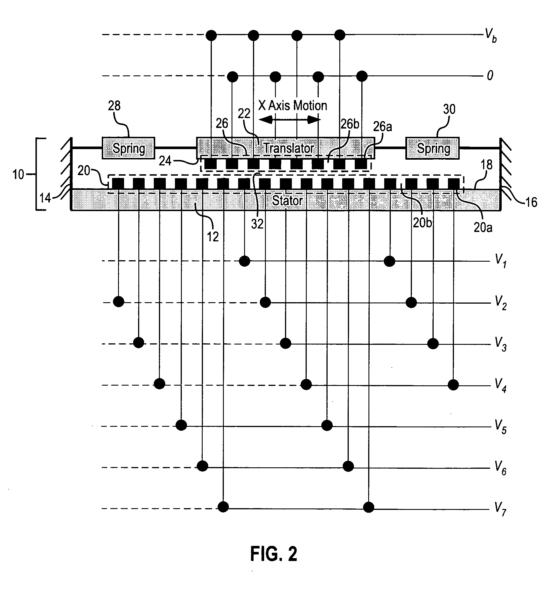
[0016]FIG. 1 schematically illustrates an exemplary linear motion electrostatic stepper motor with which the system of the present invention has been employed to allow the stepper motor to act as a precise force actuator, effectively removing the positional sensitivity from the motor response.

Problems solved by technology

However, if the voltage pattern is changed before the motor comes to rest at the location consistent with the previous state, the relative position of the translator electrodes with respect to the stator electrodes won't be known.

Method used


Image

  • System for controlling an electrostatic stepper motor
  • System for controlling an electrostatic stepper motor
  • System for controlling an electrostatic stepper motor

Examples


Embodiment Construction

[0024] Before the invention is described in detail, it is to be understood that, unless otherwise indicated, this invention is not limited to a particular circuit or components thereof, as such may vary. It is also to be understood that the terminology used herein is for purposes of describing particular embodiments only, and is not intended to be limiting.

[0025] As used in the specification and the appended claims, the singular forms “a,”“an” and “the” include plural referents unless the context clearly dictates otherwise. Thus, for example, reference to “a spring” includes a single spring as well as a plurality of springs; reference to “an electrode” includes a single electrode as well as multiple electrodes.

[0026] In this specification and in the claims that follow, reference will be made to a number of terms that shall be defined to have the following meanings, unless the context in which they are employed clearly indicates otherwise:

[0027] The term “micro motor” refers to a ...


PUM


Abstract

A system to control the fixed mass / spring mechanical resonance of the motor in conjunction with a model of the motor that estimates the present position and allows the determination of the motor stator voltage pattern which will produce the requested output force. This approach effectively eliminates the electrical restoring force from the motor dynamics and minimizes the problems associated with the varying resonant frequency of the motor.

Description

TECHNICAL FIELD [0001] The present invention generally relates to methods for motor control for a linear motion electrostatic motor but may apply to stepper motors in general. Linear motion electrostatic motors operate on stepper motor principles, i.e., they are driven by changing the voltage pattern on a set of control electrodes and allow precise control of linear motion. Changing the voltage pattern on the motor electrodes results in a known, precise change in the position of the motor after motion has stopped. BACKGROUND AND SUMMARY OF THE INVENTION [0002] Electrostatic stepper motors use a plurality of set voltage patterns to provide controlled incremental movements often referred to as steps. Changing the voltage pattern moves the stepper motor through those steps, or to a resting position at a particular step. Electrostatic stepper motors are controlled by setting a voltage pattern on an array of stator electrodes that interact with the fields on an array of translator electr...

Claims


Application Information

Patent Timeline
IPC IPC(8): H01L41/04H02N1/00
CPCH02K41/03H02P6/006H02P8/32H02P8/005H02P8/18H02P6/16
Inventor CORREDOURA, PAUL LEWIS
Owner AGILENT TECH INC
Learn More