
Method and apparatus for minimizing differential power attacks on processors

a technology of power analysis and processors, applied in the field of cryptographic systems, can solve problems such as compromising the system, difficult for an attacker to directly get at it, portable cryptographic tokens, etc., and achieve the effect of minimizing power analysis attacks on processors

Inactive Publication Date: 2007-03-08
MALIKIE INNOVATIONS LTD
View PDF29 Cites 9 Cited by
  • Summary
  • Abstract
  • Description
  • Claims
  • Application Information

AI Technical Summary

Benefits of technology

[0011] It is an object of this invention is to provide a method for minimizing power analysis attacks on processors.
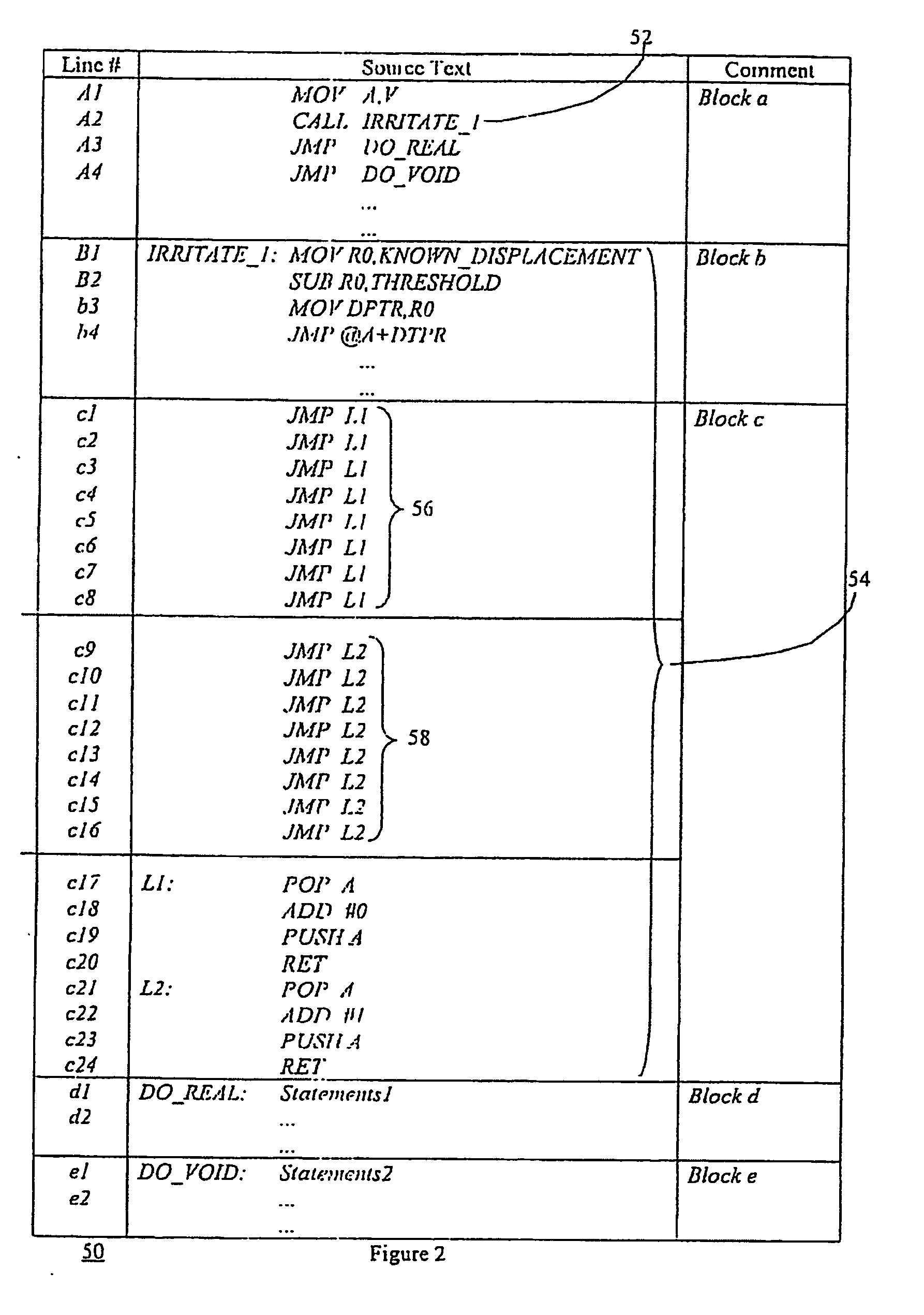
[0014] inserting code thereat for executing instructions to change program execution to a respective one of the two branches by using said distinguishing value and a base address to compute a target address, wherein for each evaluation of said condition a different number of instructions are executed, thereby minimizing the effectiveness of a differential power attack.

Problems solved by technology

This secret information must generally be stored within a secure boundary, making it difficult for an attacker to get at it directly however, various schemes or attacks have been attempted in order to obtain the secret information.
Of particular risk are portable cryptographic tokens, including smart cards and the like.
Laborious but careful analysis of end-to-end power waveforms can decompose the order of these fundamental operations performed on each bit of a secret key and thus be, analyzed to find the entire secret key, compromising the system.
The differential power analysis attack DPA) is a more powerful attack than the SPA and is much more difficult to prevent.
However, in the case of smart cards and other secure tokens, this is unfeasible.
The DPA vulnerabilities result from transistor and circuit electrical behaviors that propagate to expose logic gates, microprocessor operation and ultimately the software implementations.
In software implementation of cryptographic routines, particularly on smart cards, branches in program flow are particularly vulnerable to power analysis measurements.

Method used


Image

  • Method and apparatus for minimizing differential power attacks on processors
  • Method and apparatus for minimizing differential power attacks on processors
  • Method and apparatus for minimizing differential power attacks on processors

Examples


Embodiment Construction

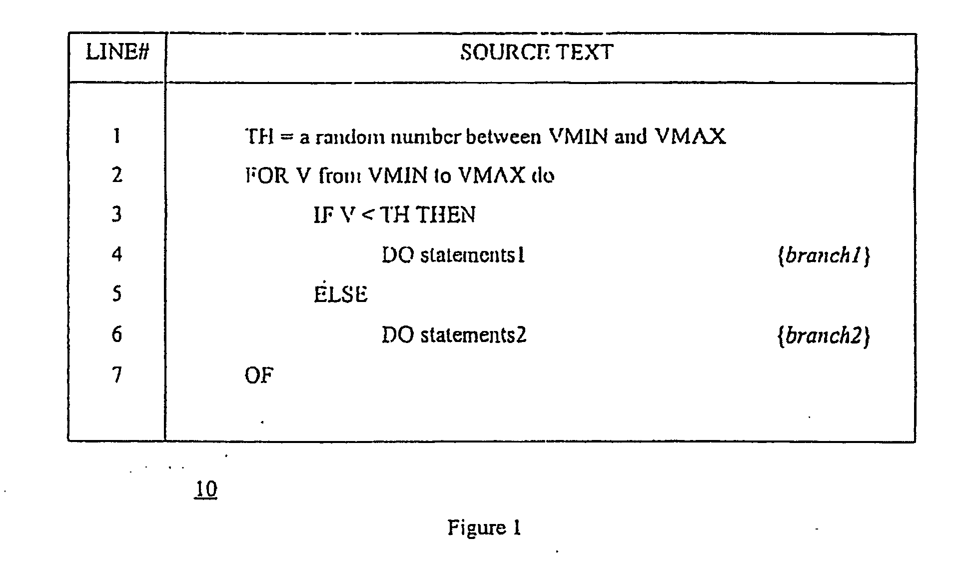
[0022] Referring to FIG. 2, a schematic diagram of a method for masking conditional jump statements in a computer program, according to an embodiment of the present invention, is shown generally by numeral 50. We assume that the following code fragments are executed by a processor and that a distinguishing value V varies within a known range and the condition is whether a threshold value TH is crossed by the distinguishing value V or not. The threshold TH is a random number in the known range having an upper limit and a lower limit VMAX and VMIN, respectively. In a generalized embodiment, the method comprises the steps of identifying a location for a conditional jump operation, and inserting at the location a call 52 to a subroutine 54, the subroutine 54 including instructions for changing the return address of the subroutine to one of two program branches to execute branch statements1 or branch statements2 in response to the result of a comparison of the distinguishing value V to t...


PUM


Abstract

A method of masking a cryptographic operation using a secret value, comprising the steps of dividing the secret value into a plurality of parts; combining with each part a random value to derive a new part such that the new parts when combined are equivalent to the original secret value; and utilizing each of the individual parts in the operation.

Description

[0001] This application is a continuation of U.S. patent application No. 09 / 900,959 filed on Jul. 10, 2001 which is a continuation-in-part of PCT Application No. PCT / CA00 / 00021 filed on Jan. 11, 2000 and PCT Application No. PCT / CA00 / 00030 filed on Jan. 14, 2000, and claims priority from Canadian Patent Application No. 2,258,338 filed on Jan. 11, 1999 and Canadian Patent Application No. 2,259,089 filed on Jan. 15, 1999 the contents of which are hereby incorporated by reference.FIELD OF THE INVENTION [0002] This invention relates to cryptographic systems and in particular to a method and apparatus for minimizing successful power analysis attacks on processors. BACKGROUND OF THE MENTION [0003] Cryptographic systems generally owe their security to the fact that a particular piece of information is kept secret, without which it is almost impossible to break the scheme. This secret information must generally be stored within a secure boundary, making it difficult for an attacker to get at...

Claims


Application Information

Patent Timeline
Patent Type & Authority Applications(United States)
IPC IPC(8): H04L9/28G06F1/00G06F7/72G06F12/14G06F21/00G06K19/073H04L9/30
CPCG06F7/725G06F9/30058G06F12/1408G06F21/52G06F21/558G06F21/75H04L9/3247G06F2207/7242G06K19/073G06K19/07363Y02B60/1225H04L9/003H04L2209/04G06F2207/7223G06F21/755Y02D10/00
Inventor PEZESHKI, FARHADLAMBERT, ROBERT J.
Owner MALIKIE INNOVATIONS LTD
Learn More