
System for biometric signal processing with hardware and software acceleration

a biometric signal and hardware acceleration technology, applied in data processing applications, instruments, individual entry/exit registers, etc., can solve the problems of requiring recall and replacement of valid cards in many financial institutions, and affecting the performance of thumbpods. , to achieve the effect of improving the performance of thumbpods

Inactive Publication Date: 2007-02-15
RGT UNIV OF CALIFORNIA
View PDF7 Cites 91 Cited by
  • Summary
  • Abstract
  • Description
  • Claims
  • Application Information

AI Technical Summary

Benefits of technology

[0007] The present invention solves these and other problems by providing a secure embedded system that uses cryptographic and biometric signal processing to provide identity authentication. In one embodiment, the secure embedded system is configured as a wireless pay-point device, called a thumbpod, for brick-and-mortar and / or e-commerce applications. In one embodiment, the thumbpod localizes a sensitive biometric template and does not require transmission of biometric data for authentication. In one embodiment, a key-generation function uses a dynamic key generator and static biometric components. An embedded system design methodology known as hardware / software acceleration transparency is provided to improve performance of the thumbpod. In one embodiment, acceleration transparency is provided in a systematic method to accelerate Java functions in both software and hardware of, for example, an encryption function.

Problems solved by technology

Though the accounts were not used fraudulently, a burdensome recall and replacement of valid cards throughout many financial institutions was required.
In brick-and-mortar credit card scenarios, photograph identification or signatures are inconsistently checked in normal purchases; hence, fraudulent transactions are commonplace.
These situations are just a few which expose the current flaw in traditional transaction protocols, which is mainly a flaw in authentication.
Identity theft results in losses of well over a billion dollars a year for credit card issuers, and is even more widespread since the advent of e-commerce on the Internet.
The primary reason for the continued success of identity theft is the lack of the ability to prove that an account is used by the genuine, authorized, consumer.

Method used


Image

  • System for biometric signal processing with hardware and software acceleration
  • System for biometric signal processing with hardware and software acceleration
  • System for biometric signal processing with hardware and software acceleration

Examples


Embodiment Construction

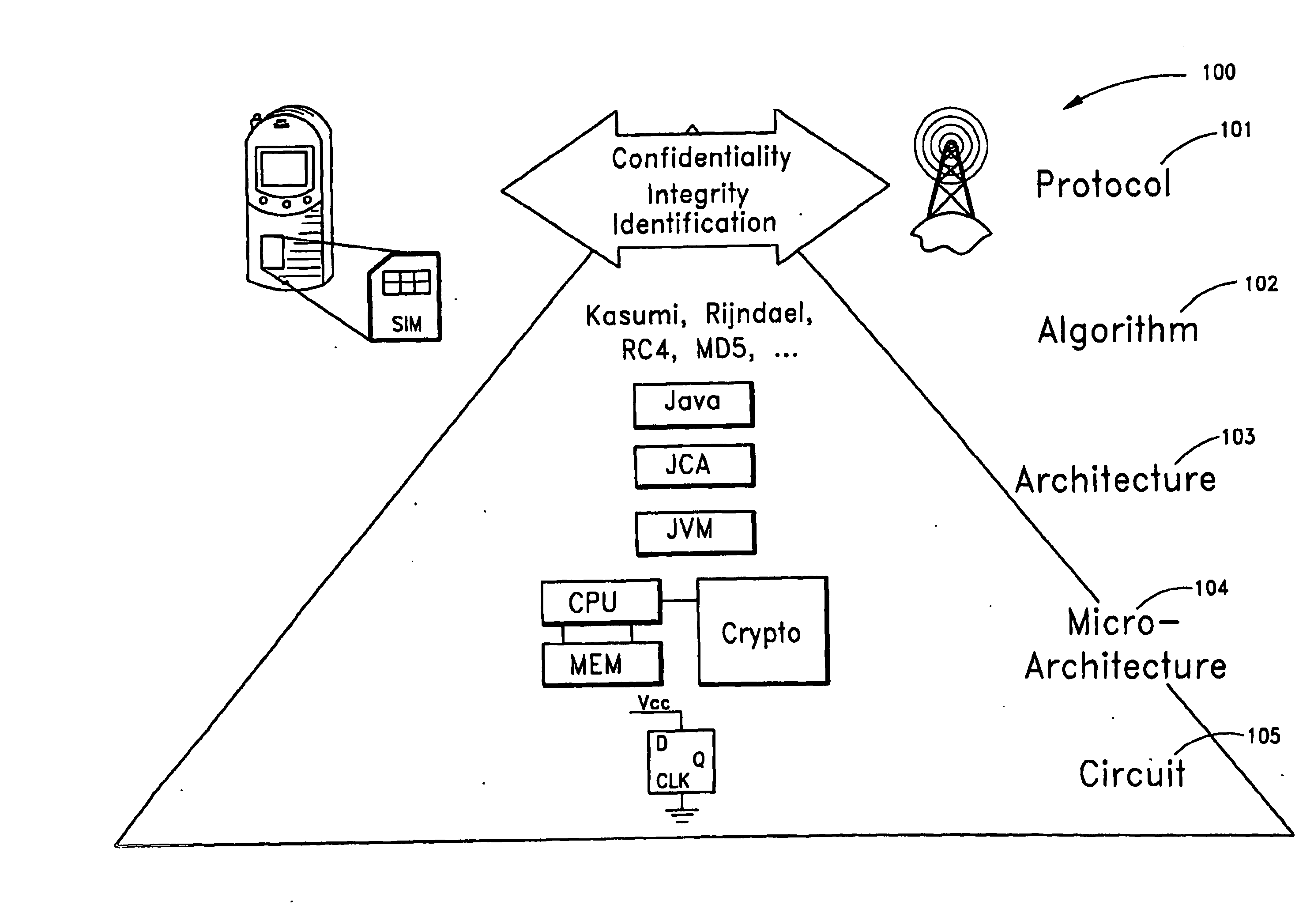
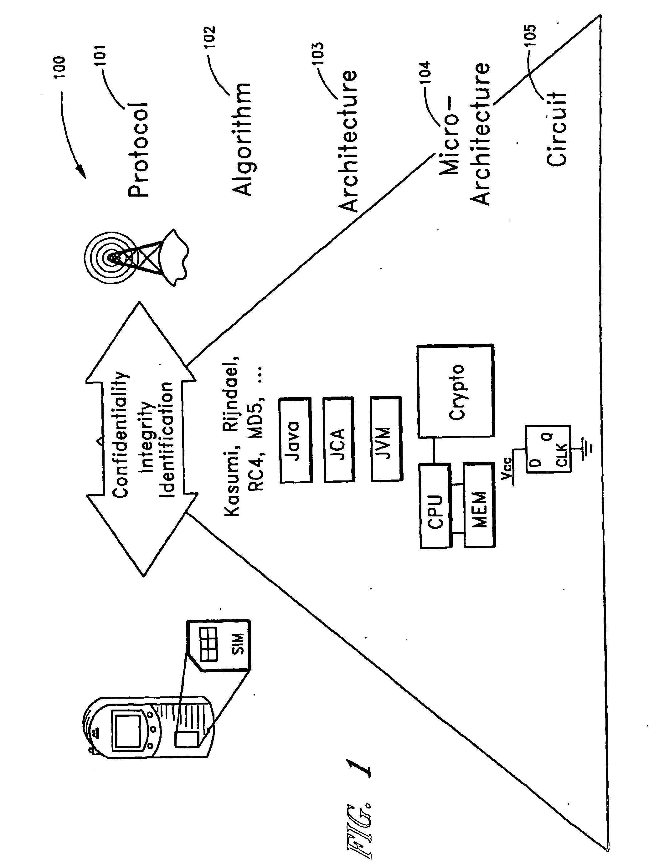
[0048]FIG. 1 shows layers of an embedded security protocol system 100. At the highest level, the system 100 includes a protocol layer 101 that provides confidentiality and identify verification. An algorithm layer 102 is provided below the protocol layer 101. The algorithm layer 101 includes one or more algorithms, such as, for example, encryption algorithms (e.g., Kasumi, Rijndael, RC4, MD5, etc.), used by the protocol layer 101. In the present disclosure, the Rijndael algorithm is used by way of example of an encryption algorithm, and not by way of limitation. An architecture layer 103 is provided below the algorithm layer 102. In one embodiment, the architecture layer 103 includes a virtual machine, such as, for example, a JAVA virtual machine. A micro-architecture layer 104 is provided below the architecture layer 103. In one embodiment, the micro-architecture layer 104 includes one or more processor architectures. A circuit layer 105 is provided below the micro-architecture lay...


PUM


Abstract

A secure embedded system that uses cryptographic and biometric signal processing acceleration is described. In one embodiment, the secure embedded system is configured as a wireless pay-point protocol for brick-and-mortar and e-commerce applications in which biometric information is localized and does not require transmission of biometric data for authentication. In one embodiment, a key-generation function uses a dynamic key generator and static biometric components. In one embodiment, an embedded system design methodology provides hardware and software acceleration transparency.

Description

REFERENCE TO RELATED APPLICATION [0001] The present application claims priority benefit if U.S. Provisional Application No. 60 / 475,242, filed Jun. 2, 2003, titled “SYSTEM FOR BIOMETRIC SIGNAL PROCESSING WITH HARDWARE AND SOFTWARE ACCELERATION,” the entire contents of which is hereby incorporated by reference.GOVERNMENT INTEREST STATEMENT [0002] Portions of the subject matter of this application were invented under a contract with an agency of the United States Government, under NSF contract No. 0098361. BACKGROUND [0003] 1. Field of the Invention [0004] The present invention relates to systems using biometric signal processing for authentication in connection with a secure communication protocol. [0005] 2. Description of the Related Art [0006] In February 2003, a computer hacker breached the security systems of Visa and MasterCard and accessed 5.6 million valid account numbers, which represents approximately 1% of all 574 million valid account numbers in the United States. Though th...

Claims


Application Information

Patent Timeline
Patent Type & Authority Applications(United States)
IPC IPC(8): H04K1/00G06F21/00G06Q20/00G07C9/00H04L9/08H04L9/32
CPCG06F21/32G06Q20/12G06Q20/4014G07C9/00087H04L9/0637H04L2209/805H04L9/16H04L9/3231H04L9/3242H04L2209/12H04L2209/56H04L9/085G07C9/257
Inventor VERBAUWHEDE, INGRID M.SCHAUMONT, PATRICK R.HWANG, DAVID D.LAI, BO-CHENGYANG, SHENGLINSAKIYAMA, KAZUOFAN, YIHODJAT, ALIREZA
Owner RGT UNIV OF CALIFORNIA
Learn More