
Binarization of an image

a binarization and image technology, applied in image enhancement, image analysis, instruments, etc., can solve the problems of complex task of implementing binarization efficiently, complex process, and increased complexity, so as to eliminate vignetting from the input image, simplify the process, and avoid variation in the properties of original images.

Inactive Publication Date: 2007-02-01
NOKIA TECHNOLOGLES OY
View PDF4 Cites 27 Cited by
  • Summary
  • Abstract
  • Description
  • Claims
  • Application Information

AI Technical Summary

Benefits of technology

[0020] It is an advantage of the invention that the separate binarization of two semi-images enables a parallel binarization of the semi-images. This renders the binarization faster.
[0021] It is further an advantage of the invention that the employed adaptive threshold may reflect local information from a range related to a target pixel, and therefore, it is not sensitive to variation in the properties of the original image.
[0022] Usually, the pixels of a digital image are arranged in columns and rows.
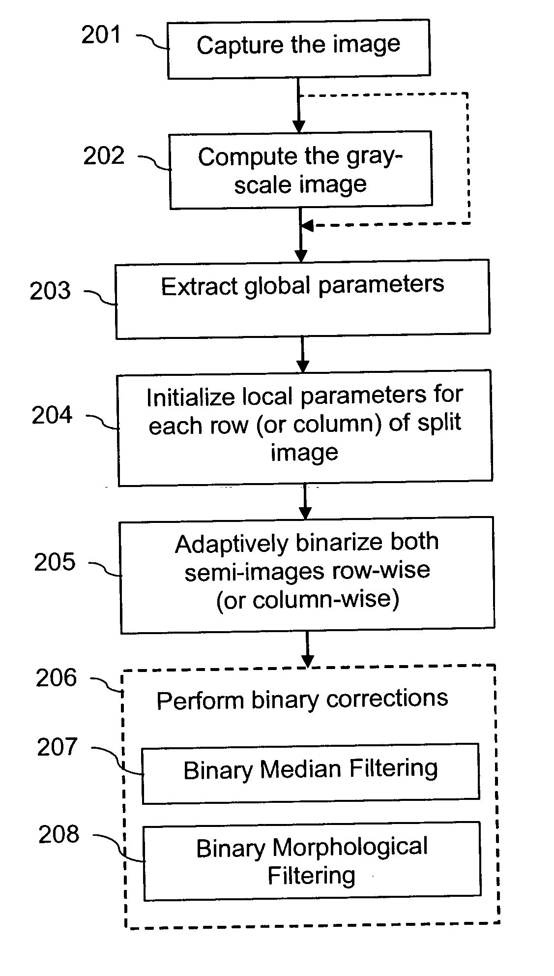
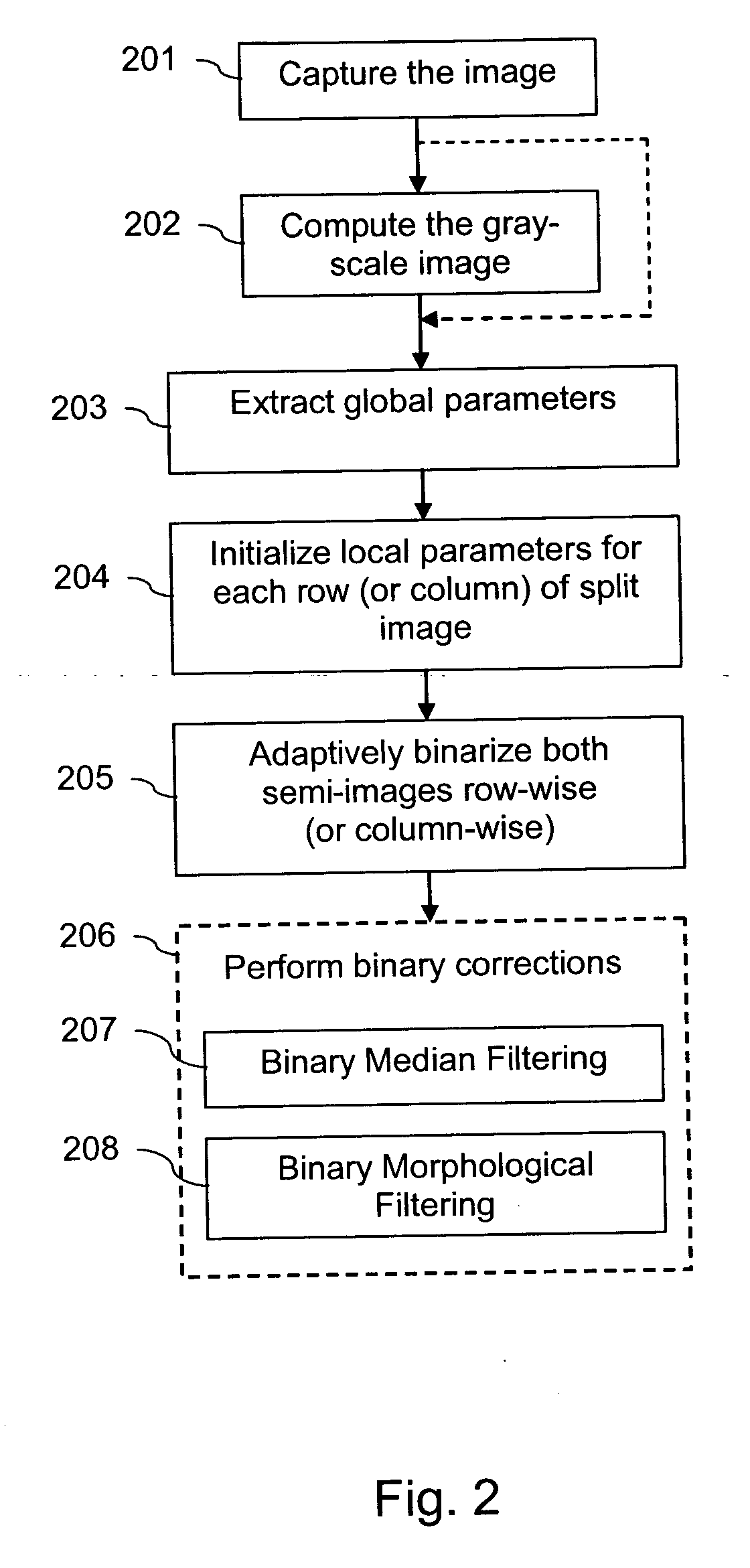
[0023] The boundary separating the semi-images may then be for instance a vertical line. The initialized local parameters may comprise in this case for each row an initial sum of pixel values in this row in the area adjacent to the vertical line. The adaptive threshold may be adapted for each pixels in each row of each semi-image based on a windowed moving sum proceeding from an initial sum associated to a respective row. Alternatively, the boundary could be for instance a horizontal line. The initialized local parameters may comprise in this case for each column an initial sum of pixel values in this column in the area adjacent to the horizontal line. The adaptive threshold may be adapted for each pixel in each column of each semi-image based on a windowed moving sum proceeding from an initial sum associated to a respective column.
[0024] The proposed initialization provides an efficient way to eliminate the vignetting from the input image. The conventional boustrophedon scanning is efficient for eliminating the bias between successive rows, but the vignetting aberration quantity is different on successive rows. In fact, its character is strongly nonlinear. One option would be to use an adaptive computational length for the moving sum. But this would complicate the process significantly. The proposed new scanning is much easier to realize. Since the scanning is not performed in alternating directions anymore, but starting for every row or column anew from the computed initializations, the vignetting is simply eliminated by the independent computation on rows or columns.
[0025] Further, the separate processing in rows or columns enables in addition a parallel processing within each semi-image.

Problems solved by technology

The task of implementing binarization efficiently can be quite complex.
Also, if binarization of hand-written notes is to be enabled, the complexity increases.
An object in a camera image is more difficult to recognize than an object in a scanner image.
The reason is that with a camera, it is more difficult to control the imaging environment than with a scanner.
Even if the user is assumed to take the image carefully, the processing of the obtained camera image may be problematic.
Firstly, the brightness of a camera image may not be uniform because of an uneven lighting or because of an aberration of the camera lens.
Thirdly, a camera image may be distorted by sensor noise added to the captured image, as well as by optical blur and vignetting that are due to the optical system of the camera, namely the camera lenses.
These problems are especially significant in camera images that are not well focused.
Even if a particular set of parameters works nicely for one image, these parameters will most likely not be suitable for other images.
Moreover, even if an optimal parameter is computed carefully, the binarization approach may fail to preserve important details of the structure of an object.
Consequently, several problems have to be considered when binarizing a camera image.
But if the background or the noise characteristics are non-uniform, this approach may result in large errors.

Method used


Image

  • Binarization of an image
  • Binarization of an image
  • Binarization of an image

Examples


Embodiment Construction

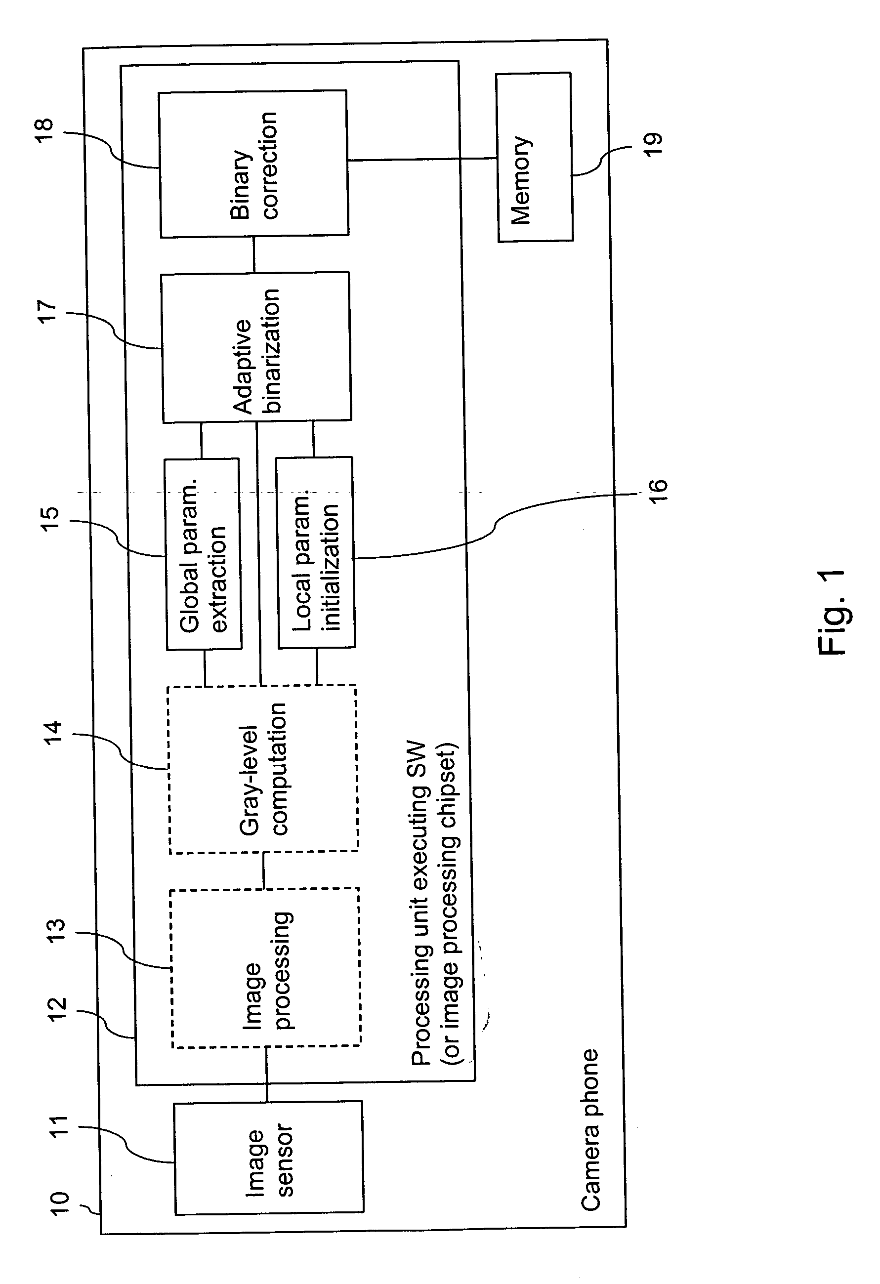
[0053]FIG. 1 is a schematic block diagram of an electronic device, which enables an efficient binarization in accordance with an embodiment of the invention.

[0054] By way of example, the electronic device is a camera phone 10, that is, a mobile phone comprising embedded camera functions. It is to be understood, though, that it could be any other kind of electronic device that benefits from an efficient image binarization.

[0055] The camera phone 10 includes an image sensor 11, for instance a CCD (charge coupled device) sensor.

[0056] The camera phone 10 further includes a processing unit 12 that is adapted to execute various software program codes. The software codes include an optional image processing code 13 and binarization-related software program codes. The image processing code 13 can realize for example an imaging chain or a JPG image generator. Together with the image sensor 11, it forms a conventional image capturing portion. The binarization-related software program code...


PUM


Abstract

For binarizing an image, which is composed of pixels, the image is split into two semi-images. Local parameters are initialized based on values of pixels that lie in an area adjacent to a boundary separating the semi-images. A binarization is then performed separately for each of the semi-images using an adaptive threshold, wherein the adaptive threshold is calculated for each of the semi-images proceeding from the initialized local parameters.

Description

FIELD OF THE INVENTION [0001] The invention relates to a method for binarizing an image, to an image processing chipset and an electronic device supporting a binarization of an image, and to a software program product, in which a software code for binarizing an image is stored. BACKGROUND OF THE INVENTION [0002] Information is frequently presented as a color image or a grayscale image, even though its content could be presented as a binary image. Examples for such information are printed documents, hand written notes, barcodes, some of the information displayed on TV screens both on tele-text and on the normal screen, some presentations on computer monitors, etc. [0003] In some situations, it may be desired to convert such a color or grayscale image by means of binarization into a binary-valued image, for example in order to facilitate a document analysis or to reduce the data amount. In most document imaging systems, a binarization process typically precedes the document analyzing ...

Claims


Application Information

Patent Timeline
IPC IPC(8): G06K9/36G06V30/10G06V30/162
CPCG06K9/38G06T7/0081G06T2207/30176G06T2207/20021G06T2207/20148G06T2207/20012G06T7/11G06T7/136G06V30/10G06V30/162G06T5/00
Inventor BURIAN, ADRIANVEHVILAINEN, MARKKU
Owner NOKIA TECHNOLOGLES OY
Learn More