
Device for spectroscopy using charged analytes

a technology of charged analytes and spectroscopy, which is applied in the direction of electrolysis, particle separator tubes, beam/ray deflecting arrangements, etc., can solve the problems of high thermal strain of the membrane by the electron beam, and the known ion mobility spectrometer is therefore not suitable for maintenance-free long-term us

Inactive Publication Date: 2007-02-01
EXCITECH GMBH
View PDF18 Cites 4 Cited by
  • Summary
  • Abstract
  • Description
  • Claims
  • Application Information

AI Technical Summary

Benefits of technology

[0012] Proceeding from this related art, the present invention is based on the object of providing a device for spectroscopy using charged analytes which is improved in regard to the stability.
[0017] In a special embodiment, the membrane is implemented as multilayered, in particular having an oxide layer and a nitride layer. Using this multilayered design, the mechanical stability may be improved.
[0021] In a further preferred embodiment, the membrane is implemented without metallic electrodes. Since the attenuation of an electron beam is greater the greater the atomic number Z of the material, an electron beam in metals having especially high atomic number Z is attenuated especially strongly. For low energy absorption in the membrane, it is thus advantageous if the membrane is free of layers made of metals having a high atomic number Z if possible.
[0023] In a preferred embodiment, an intermediate chamber is located between the charging chamber and the drift chamber, in which a deflector electrode is implemented, with the aid of which the charged analytes collected in the intermediate chamber are transportable into the drift chamber. Therefore, in this case, metal coating of the membrane may be dispensed with, which results in improved transmission of the membrane.

Problems solved by technology

However, a disadvantage of the known ion mobility spectrometer is the high thermal strain of the membrane by the electron beam, because of which a support grating is situated on the entry side of the membrane, which mechanically stabilizes the membrane.
The known ion mobility spectrometer is thus not suitable for maintenance-free long-term use.

Method used


Image

  • Device for spectroscopy using charged analytes
  • Device for spectroscopy using charged analytes
  • Device for spectroscopy using charged analytes

Examples


Embodiment Construction

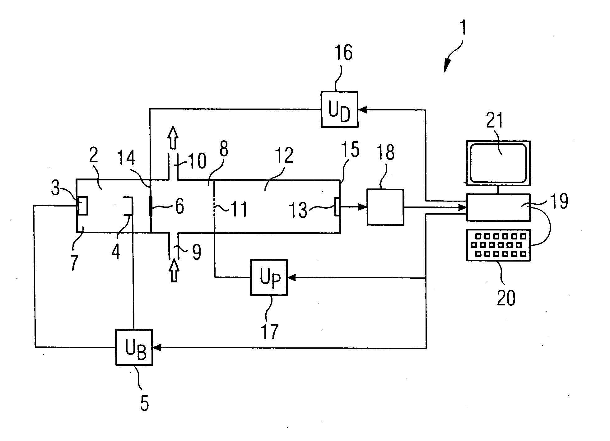
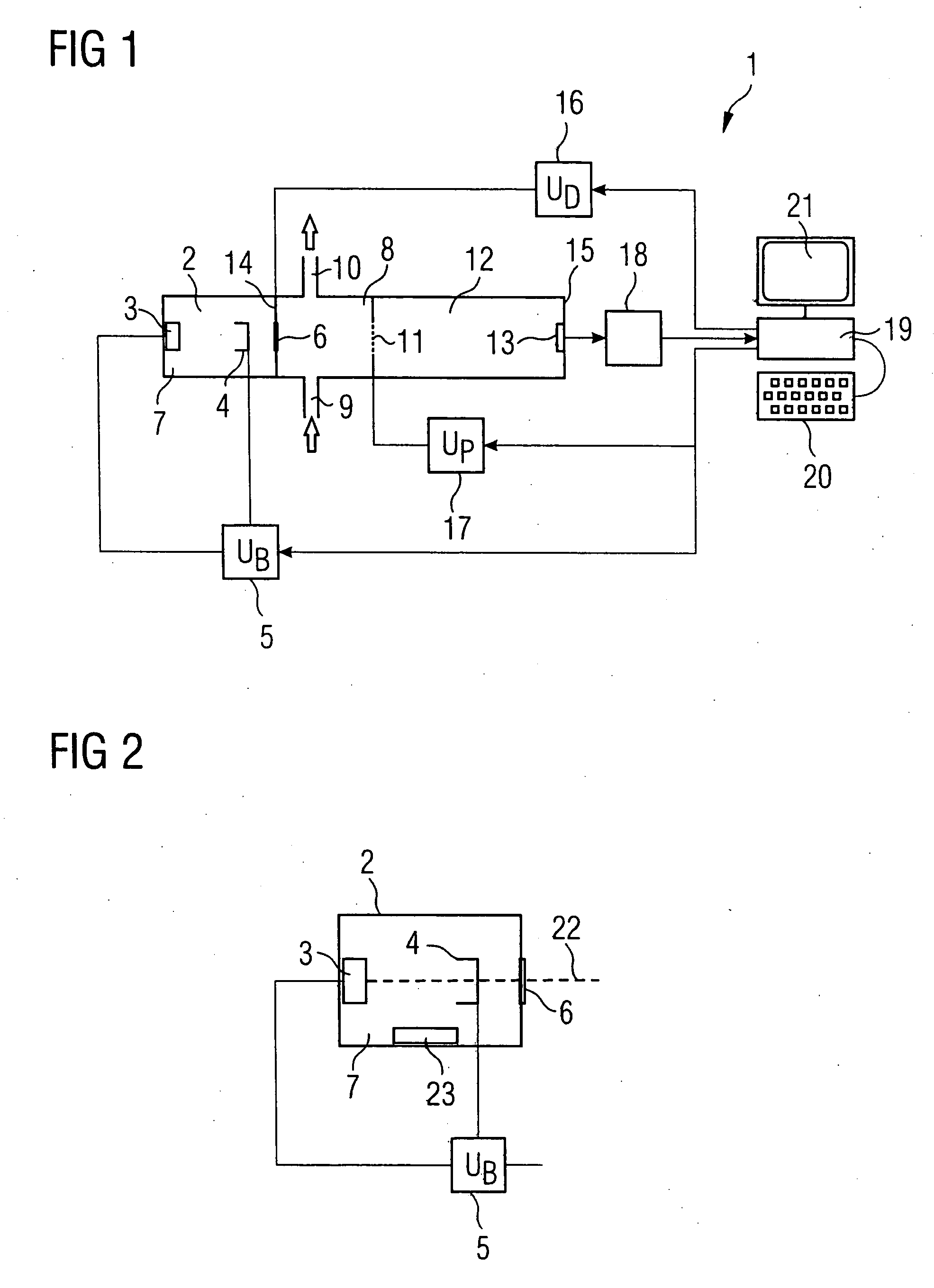
[0036]FIG. 1 shows an ion mobility spectrometer 1, which has an electron generator 2 for generating free electrons. This electron generator 2 comprises an electron emitter 3, which is a heating coil, for example, which emits electrons through thermionic emission. The electron generator 2 also has an acceleration anode 4. An acceleration voltage UB, which is generated by an acceleration voltage source 5, is applied between the electron emitter 3 and the acceleration anode 4. A gas-tight electron-permeable membrane 6 is located in the beam direction behind the acceleration anode 4, which separates the generator chamber 7 from an ionization chamber 8, which has the function of the charging chamber in the ion mobility spectrometer 1 as in all other embodiments. A sample gas inlet 9 and a sample gas outlet 10 are connected to the ionization chamber 8.

[0037] A barrier grating 11 in turn separates the ionization chamber 8 from a drift chamber 12, which comprises multiple annular electrode...


PUM

PropertyMeasurementUnit
Timeaaaaaaaaaa
Thicknessaaaaaaaaaa
Ionizing radiationaaaaaaaaaa

Abstract

A device for spectroscopy using charged analytes has an electron generator, which sends electrons through membrane into a charging chamber. The thermal strain of the membrane may be lowered significantly if a material is selected for the membrane which contains at least one component from the group of oxides, nitrides, and carbides with at least one of the elements B, Al, C, Si, and Ti or polysilicon.

Description

CROSS-REFERENCE TO RELATED APPLICATIONS [0001] This application claims priority of German Application No. 102005028930.4 filed on June 22, 2005. FIELD OF THE INVENTION [0002] The present invention relates to a device for spectroscopy using charged analytes having a gas chamber, which has a gas inlet and a charging chamber for forming charged analytes, a detector for detecting the charged analytes, a drift generator, which causes drift of charged analytes to the detector, and having an electron generator, which is separated from the gas chamber by a gas-tight membrane permeable to electrons and sends the electrons through the membrane into the charging chamber. BACKGROUND OF THE INVENTION [0003] A device of this type for ion mobility spectroscopy is known from DE 196 27 621 A1. The gas chamber is composed of a drift chamber and a partial chamber of a reaction chamber therein. A thermal electron emitter for generating free electrons is located in a further evacuated partial chamber of...

Claims


Application Information

Patent Timeline
IPC IPC(8): H01J49/00
CPCG01N27/622G01N27/62G01N27/64
Inventor ULRICH, ANDREASBAETHER, WOLFGANGWIESER, JOCHEN
Owner EXCITECH GMBH
Learn More