
Cylindrical cell and manufacturing method thereof

a technology of cylindrical cells and manufacturing methods, applied in the field of cylindrical batteries, can solve the problems of high contact resistance between the metal case and the negative electrode collector, and peeling of the negative electrode collector from the negative electrode plate,

Active Publication Date: 2007-01-25
PANASONIC CORP
View PDF6 Cites 22 Cited by
  • Summary
  • Abstract
  • Description
  • Claims
  • Application Information

AI Technical Summary

Benefits of technology

"The present invention relates to a method for manufacturing a cylindrical battery. The method involves spirally winding electrodes with a separator in between, and welding them to a collector. The electrodes are then accommodated in a metal case, and the collector is welded to the case. The battery is then sealed and the connection resistance is reduced. The method also includes forming projections on the bottom of the metal case and the other collector, and using resistance welding to connect them. The resulting battery has high-rate charge and discharge capabilities, and stable connection even at high internal pressure. The method also ensures even welding of all the projections and improves the connection resistance."

Problems solved by technology

However, the aforementioned conventional structure has a problem that contact resistance between the metal case and the negative electrode collector is high because the metal case and the collector are connected to each other at one welding point.
This deformation may cause peeling of the negative electrode collector from the negative electrode plate.

Method used


Image

  • Cylindrical cell and manufacturing method thereof
  • Cylindrical cell and manufacturing method thereof
  • Cylindrical cell and manufacturing method thereof

Examples


embodiment 1

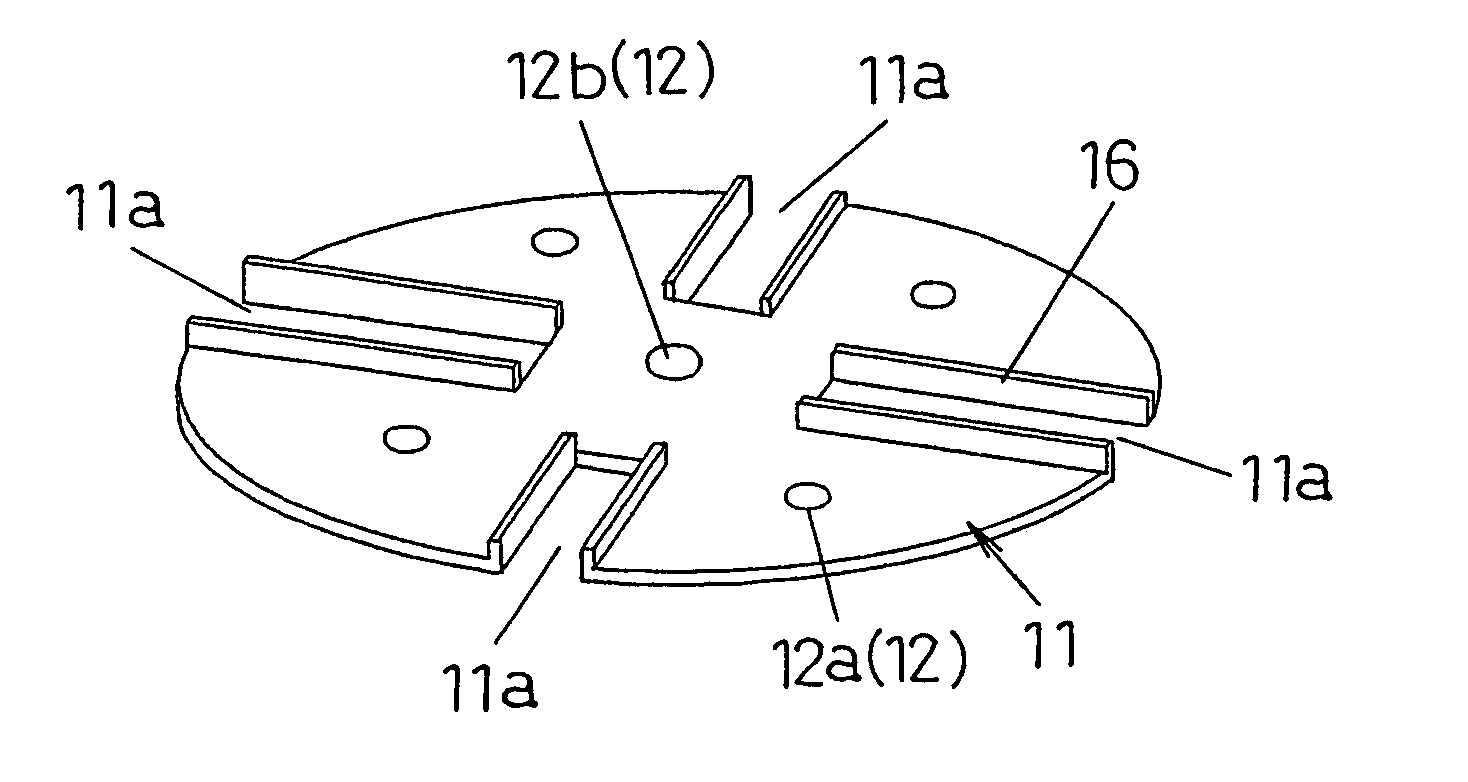
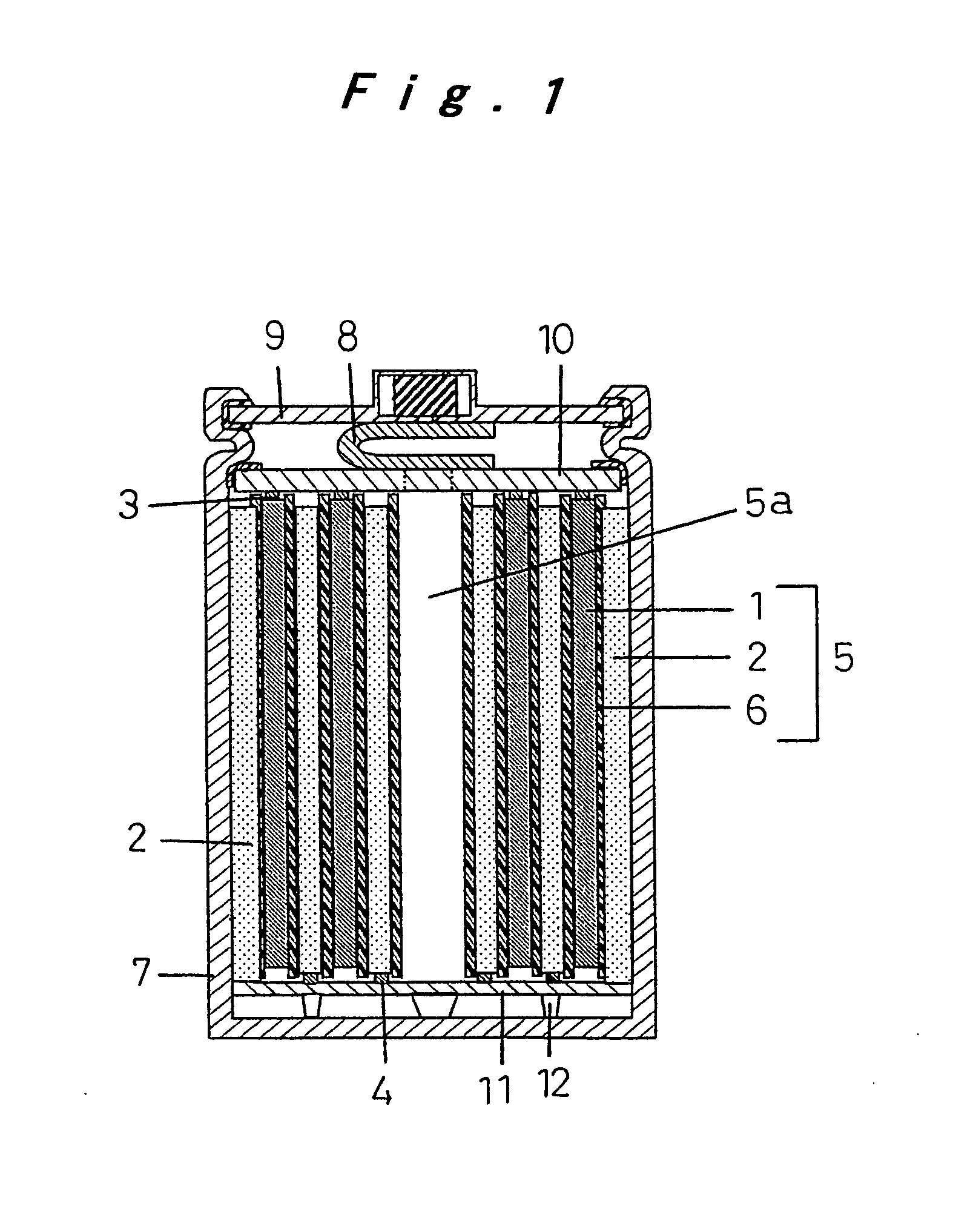
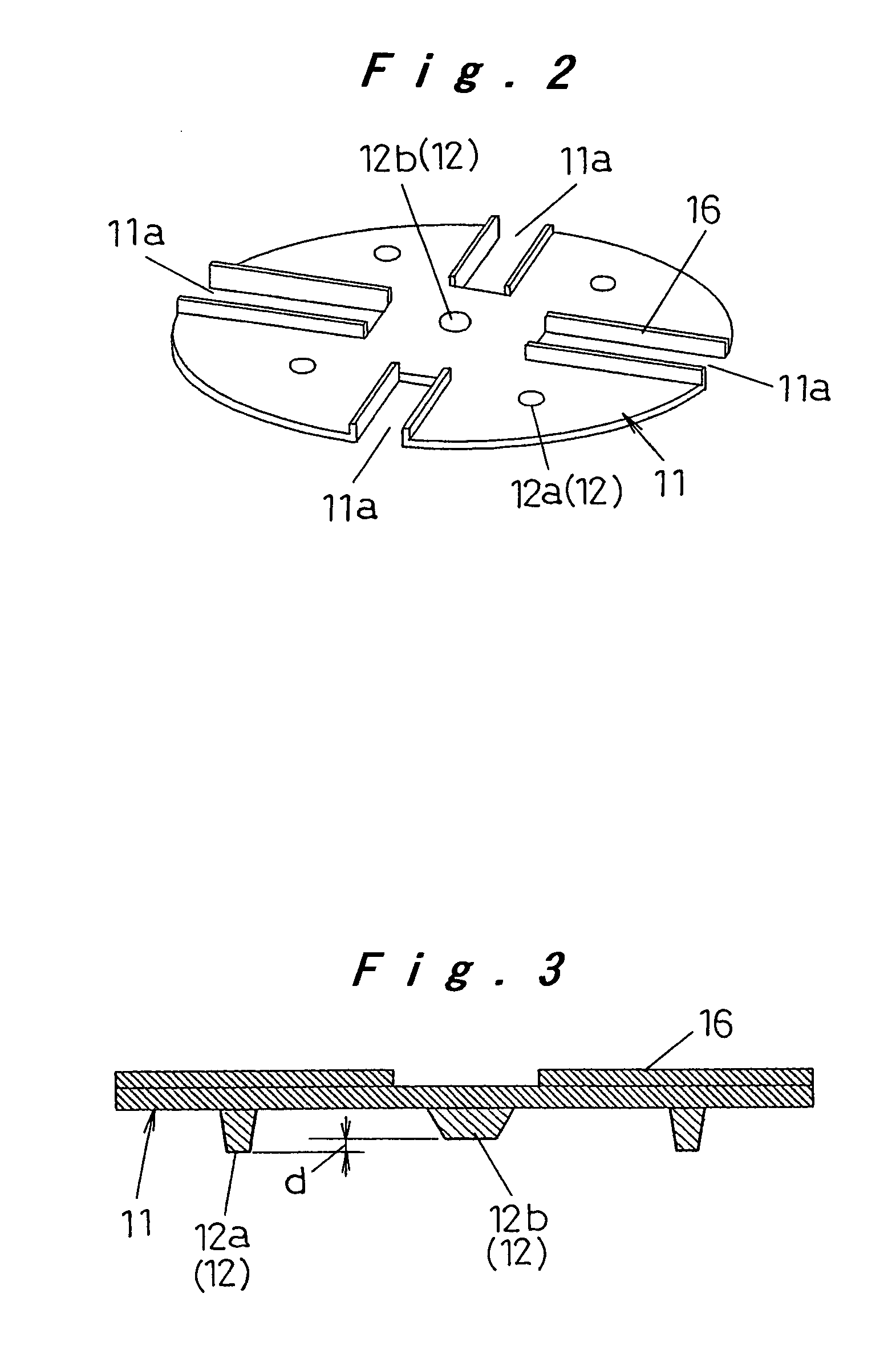
[0025] First, a cylindrical battery and a method for manufacturing the same according to a first embodiment of the present invention are described, with reference to FIGS. 1 to 7.

[0026]FIG. 1 is a cross-sectional view schematically showing the cylindrical battery of the present embodiment. In FIG. 1, an electrode plate assembly 5 of the cylindrical battery is formed by spirally winding a strip-like positive electrode plate 1 and a strip-like negative electrode plate 2 that are stacked with a strip-like separator 6 interposed therebetween. A core material 3 of the positive electrode plate 1 projects upward from the electrode plate assembly 5. A core material 4 of the negative electrode plate 2 projects downward from the electrode plate assembly 5. A positive electrode collector 10 is welded to a projecting portion of the core material 3 of the positive electrode plate 1, which projects upward from the electrode plate assembly 5. A negative electrode collector 11 is welded to a proje...

embodiment 2

[0036] A cylindrical battery and a method for manufacturing the cylindrical battery according to a second embodiment of the present invention are described, with reference to FIGS. 8 to 10. The same components as those in the first embodiment are labeled with the same reference numerals as those in the first embodiment and the description thereof is omitted. That is, only a difference between the first and second embodiments is mainly described.

[0037] In the first embodiment, the projections 12a and 12b are provided on the lower surface of the negative electrode collector 11 and the negative electrode collector 11 is welded to the inner bottom surface of the metal case 7 via the projections 12a and 12b. However, in the present embodiment, projections 15 (15a and 15b) are provided on the inner bottom surface of the metal case 7 and are welded to the lower surface of the negative electrode collector 11 in the form of a flat surface.

[0038] In FIG. 8, a plurality of projections 15a pr...

example

[0043] A specific example of the present invention is now described. A cylindrical battery A of the present invention is a nickel metal hydride rechargeable battery having a diameter of 33 mm, a height of 61 mm, and a nominal capacitance of 6000 mAh. The structure of that cylindrical battery and a method for manufacturing that cylindrical battery are now described in detail.

[0044] The cylindrical battery A used a strip-like positive electrode plate of sintered nickel having a thickness of 0.5 mm and a strip-like negative electrode plate formed of hydrogen-absorption alloy having a thickness of 0.3 mm. Core materials of the positive electrode plate and the negative electrode plate were exposed at side ends in a width direction that were opposite to each other. A separator was interposed between the positive and negative electrode plates. The positive and negative electrode plates were arranged in such a manner that the exposed core materials of the positive and negative electrode pl...


PUM

PropertyMeasurementUnit
heightaaaaaaaaaa
heightaaaaaaaaaa
diameteraaaaaaaaaa

Abstract

A cylindrical battery includes: an electrode plate assembly (5); a positive electrode collector (10) welded to a projecting portion of a core material for a positive electrode of the electrode plate assembly (5); a negative electrode collector (11) that includes a plurality of projections (12) at its lower surface and is welded to a projecting portion of a core material for a negative electrode of the electrode plate assembly (5) at its upper surface; a metal case (7) for accommodating the electrode plate assembly (5) to which the positive and negative electrode collectors (10, 11) are jointed, so as to arrange the negative electrode collector (11) down, the projections (12) of the negative electrode collector (11) being welded to an inner bottom surface of the metal case (7); an electrolyte poured into the metal case (7); and a sealing member (9), electrically insulated from the metal case (7), for sealing a top of the metal case (7), wherein the projections (12) of the negative electrode collector (11) are arranged at a plurality of locations in a region between a portion opposed to a hollow cylindrical portion (5a) of the electrode plate assembly (5) and a peripheral portion. Thus, it is possible to provide the cylindrical battery that is favorable when large current discharge is performed and that has high pressure resistance of the metal case.

Description

TECHNICAL FIELD [0001] The present invention relates to a cylindrical battery including an electrode plate assembly that is spirally wound and a method for manufacturing that cylindrical battery. BACKGROUND ART [0002] There are various types of cylindrical batteries that are typified by a nickel-cadmium battery and a nickel metal hydride battery. Those cylindrical batteries are widely used in various applications, for example, as a power source for a cellular phone or a notebook computer, because they have high reliability and maintenance is easy. In recent years, development of cylindrical batteries suitable for large current discharge as a power source for an electric-assist bicycle, a lawnmower, and an electric vehicle has been demanded. [0003] The cylindrical battery for a large current is formed by accommodating an electrode plate assembly in a metal battery case. The electrode plate assembly is formed by spirally winding a strip-like positive electrode plate and a strip-like n...

Claims


Application Information

Patent Timeline
Patent Type & Authority Applications(United States)
IPC IPC(8): H01M2/06H01M2/02H01M2/08H01M6/10H01M10/04H01M2/26H01M50/533H01M50/536H01M50/541
CPCH01M2/022H01M2/266Y10T29/4911Y10T29/49114H01M2/345Y02E60/10H01M50/107H01M50/578Y02P70/50H01M50/536H01M50/533
Inventor BITO, SEIJIYONEYAMA, SATOSHIKATO, MASAHIKO
Owner PANASONIC CORP
Learn More