Cylindrical cell and manufacturing method thereof
a technology of cylindrical cells and manufacturing methods, applied in the field of cylindrical batteries, can solve the problems of high contact resistance between the metal case and the negative electrode collector, and peeling of the negative electrode collector from the negative electrode plate,
- Summary
- Abstract
- Description
- Claims
- Application Information
AI Technical Summary
Benefits of technology
Problems solved by technology
Method used
Image

Examples
embodiment 1
[0025]First, a cylindrical battery and a method for manufacturing the same according to a first embodiment of the present invention are described, with reference to FIGS. 1 to 7.
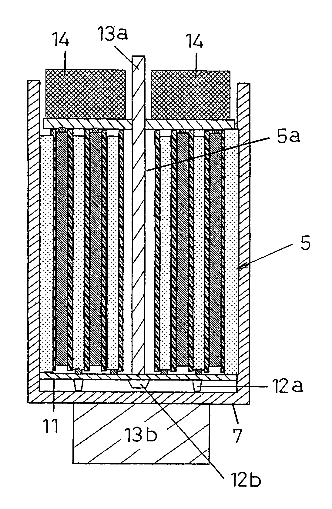
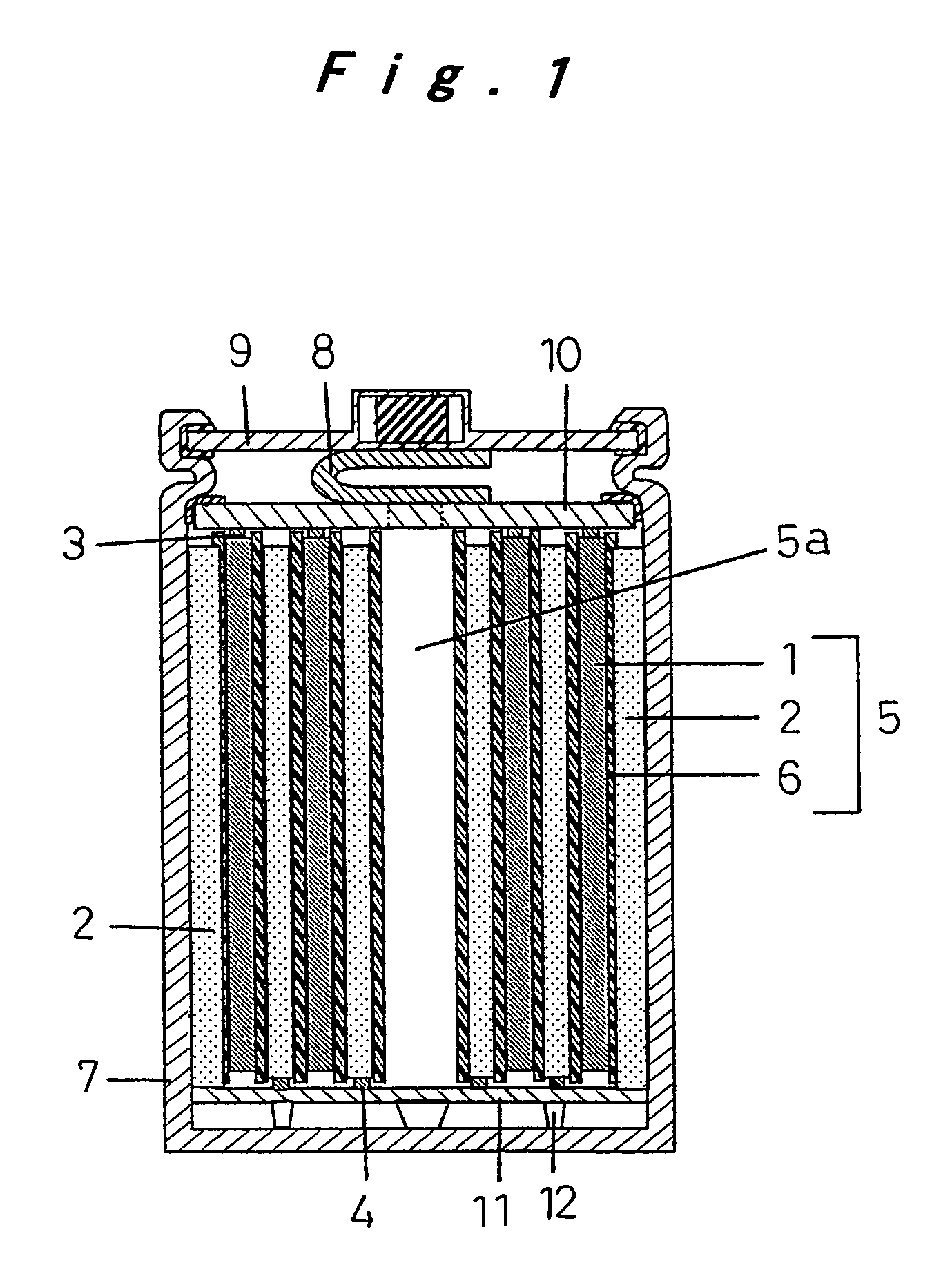
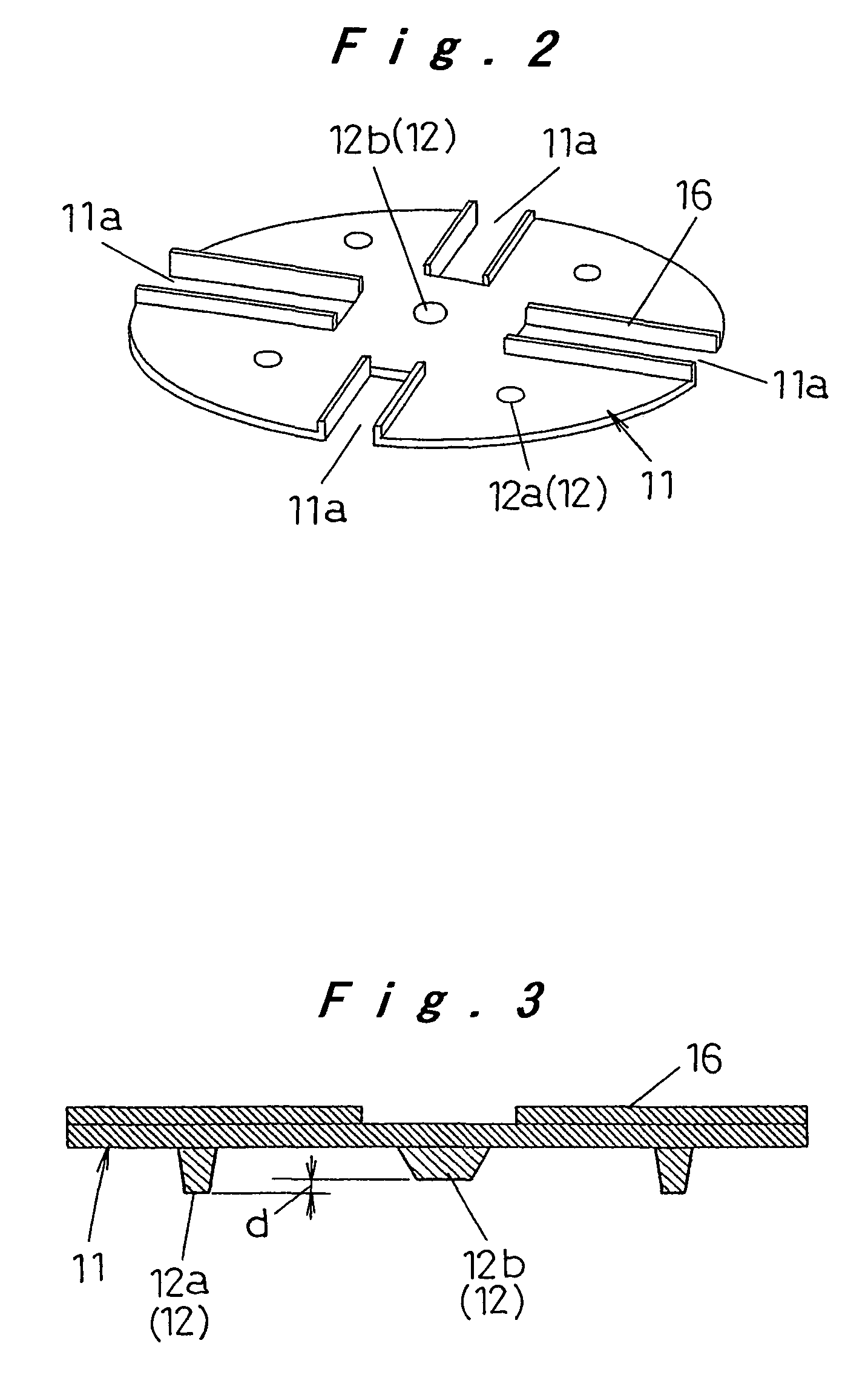
[0026]FIG. 1 is a cross-sectional view schematically showing the cylindrical battery of the present embodiment. In FIG. 1, an electrode plate assembly 5 of the cylindrical battery is formed by spirally winding a strip-like positive electrode plate 1 and a strip-like negative electrode plate 2 that are stacked with a strip-like separator 6 interposed therebetween. A core material 3 of the positive electrode plate 1 projects upward from the electrode plate assembly 5. A core material 4 of the negative electrode plate 2 projects downward from the electrode plate assembly 5. A positive electrode collector 10 is welded to a projecting portion of the core material 3 of the positive electrode plate 1, which projects upward from the electrode plate assembly 5. A negative electrode collector 11 is welded to a project...
embodiment 2
[0036]A cylindrical battery and a method for manufacturing the cylindrical battery according to a second embodiment of the present invention are described, with reference to FIGS. 8 to 10. The same components as those in the first embodiment are labeled with the same reference numerals as those in the first embodiment and the description thereof is omitted. That is, only a difference between the first and second embodiments is mainly described.
[0037]In the first embodiment, the projections 12a and 12b are provided on the lower surface of the negative electrode collector 11 and the negative electrode collector 11 is welded to the inner bottom surface of the metal case 7 via the projections 12a and 12b. However, in the present embodiment, projections 15 (15a and 15b) are provided on the inner bottom surface of the metal case 7 and are welded to the lower surface of the negative electrode collector 11 in the form of a flat surface.
[0038]In FIG. 8, a plurality of projections 15a project...
example
[0043]A specific example of the present invention is now described. A cylindrical battery A of the present invention is a nickel metal hydride rechargeable battery having a diameter of 33 mm, a height of 61 mm, and a nominal capacitance of 6000 mAh. The structure of that cylindrical battery and a method for manufacturing that cylindrical battery are now described in detail.
[0044]The cylindrical battery A used a strip-like positive electrode plate of sintered nickel having a thickness of 0.5 mm and a strip-like negative electrode plate formed of hydrogen-absorption alloy having a thickness of 0.3 mm. Core materials of the positive electrode plate and the negative electrode plate were exposed at side ends in a width direction that were opposite to each other. A separator was interposed between the positive and negative electrode plates. The positive and negative electrode plates were arranged in such a manner that the exposed core materials of the positive and negative electrode plate...
PUM
| Property | Measurement | Unit |
|---|---|---|
| height | aaaaa | aaaaa |
| height | aaaaa | aaaaa |
| height | aaaaa | aaaaa |
Abstract
Description
Claims
Application Information
 - R&D
- Intellectual Property
- Life Sciences
- Materials
- Tech Scout
- Unparalleled Data Quality
- Higher Quality Content
- 60% Fewer Hallucinations
Browse by: Latest US Patents, China's latest patents, Technical Efficacy Thesaurus, Application Domain, Technology Topic, Popular Technical Reports.
© 2025 PatSnap. All rights reserved.Legal|Privacy policy|Modern Slavery Act Transparency Statement|Sitemap|About US| Contact US: help@patsnap.com