Motor driving device and motor driving method
a technology of motor driving and driving method, which is applied in the direction of motor/generator/converter stopper, electronic commutator, dynamo-electric converter control, etc., can solve the problem of inability to detect the rotor position by the above method, the accuracy of finding the peak value of pulse current is not good, and the motor is not suitable for inexpensive motors. problems, to achieve the effect of improving the start speed, excellent response signal quality and low cos
- Summary
- Abstract
- Description
- Claims
- Application Information
AI Technical Summary
Benefits of technology
Problems solved by technology
Method used
Image
Examples
first embodiment
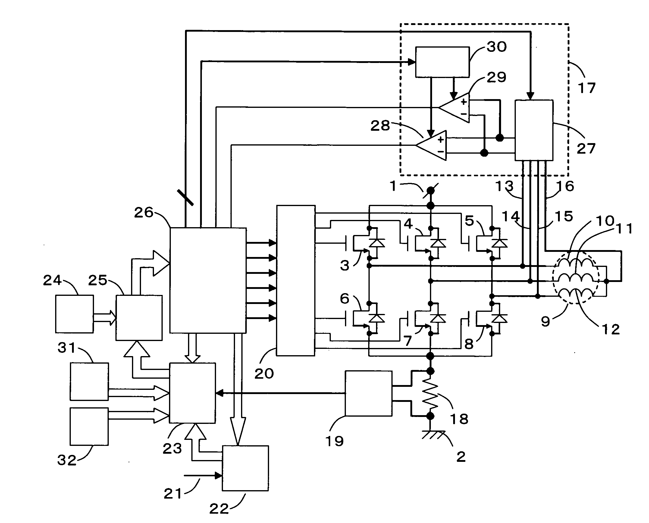
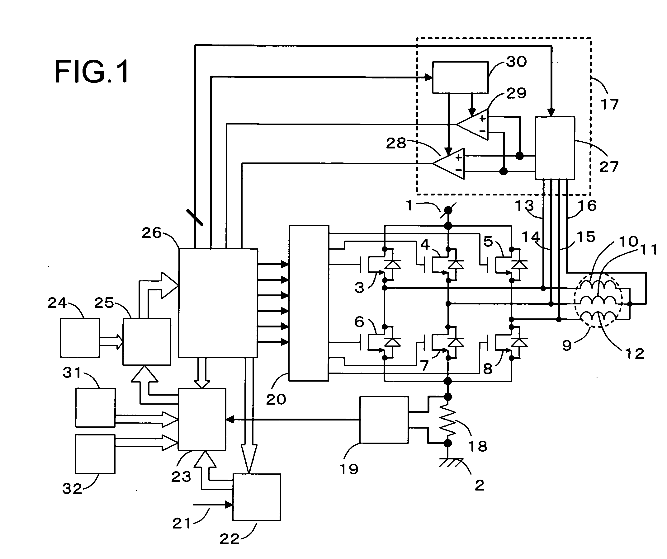
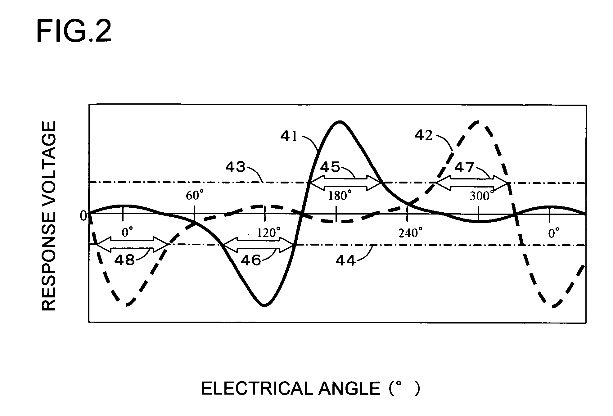
[0097]FIG. 1 is a block diagram showing a circuit constitution of a motor driving device according to first embodiment of the present invention. Referring to FIG. 1, the motor driving device includes a high-potential power line 1, a low-potential power line 2, a U-phase high-potential drive transistor 3, a V-phase high-potential drive transistor 4, a W-phase high-potential drive transistor 5, a U-phase low-potential drive transistor 6, a V-phase low-potential drive transistor 7, a W-phase low-potential drive transistor 8, a motor 9, a U-phase motor winding 10, a V-phase motor winding 11, a W-phase motor winding 12, a U-phase terminal line 13, a V-phase terminal line 14, a W-phase terminal line 15, a neutral point terminal line 16, a phase comparison control block 17, a current detection resistor 18, a current detection amplifier 19, a pre-driver 20, an external command signal 21, a component torque generation block 22, a torque comparison block 23, a PWM on-pulse generation block 24...
second embodiment
[0182] A motor driving method according to a second embodiment of the present invention is characterized in that it uses a response signal value provided by an inductive action when a current of a rotor position search pulse has a predetermined value. FIG. 5 is a view showing characteristics of a response signal generated between a W-phase terminal line 15 having a current of zero and a neutral point terminal line 16 with respect to the rotor position when a rotor position search pulse is applied from a U-phase winding terminal to a V-phase winding terminal in two cases having different current levels of the rotor position search pulse. Referring to FIG. 5, a curved line 51 designates the characteristics of the response signal when the rotor position search pulse current is high and the response signal characteristics 51 includes a main peak 52, a main bottom 53, a sub peak 54 and a sub bottom 55. In addition, a curved line 56 designates the characteristics of the response signal wh...
third embodiment
[0184] A motor driving method according to a third embodiment of the present invention is characterized in that a predetermined order is set when a current is applied from a certain phase winding to another phase winding, that is, when a certain combination of the two phases is selected with priority at the time of applying a rotor position search pulse. The phase windings to which the current is to be applied are determined by selecting the high-potential drive transistor and the low-potential drive transistor when the rotor position search pulse is applied. FIG. 7 shows electrical angular positions which can determine the rotor position when series windings of the two phases are selected from three phase windings and the rotor position search pulse is applied thereto. [0185] (i) The rotor positions which can be detected by applying the rotor position search pulse current from a U-phase winding to V-phase winding are indicated in regions 71 and 72. [0186] (ii) The rotor positions w...
PUM
 Abstract
Description
Claims
Application Information
 - R&D
- Intellectual Property
- Life Sciences
- Materials
- Tech Scout
- Unparalleled Data Quality
- Higher Quality Content
- 60% Fewer Hallucinations
Browse by: Latest US Patents, China's latest patents, Technical Efficacy Thesaurus, Application Domain, Technology Topic, Popular Technical Reports.
© 2025 PatSnap. All rights reserved.Legal|Privacy policy|Modern Slavery Act Transparency Statement|Sitemap|About US| Contact US: help@patsnap.com


