
Diesel generating set parallel operation system for safety source of thermal power plant

A technology for diesel generator sets and security power supplies, which is applied in emergency power supply arrangements, electrical components, circuit devices, etc., and can solve the problems of low power supply reliability, slow startup speed, and low startup success rate.

Active Publication Date: 2015-12-23
SHANGHAI COOLTECH POWER
View PDF3 Cites 7 Cited by
  • Summary
  • Abstract
  • Description
  • Claims
  • Application Information

AI Technical Summary

Problems solved by technology

However, at present, diesel generator sets and their operation control and parallel systems are used as security power solutions for thermal power plants due to the existence of automatic degree, type, accuracy, etc. Insufficient, resulting in too long start-up and parallel process during emergency start-up, low start-up success rate, and low power supply reliability. Such shortcomings have a great impact on the reliability and stable operation quality of the security power supply
With the continuous improvement of safety production and automation level requirements of large-scale thermal power plants, the problems of low self-starting success rate and slow start-up speed of diesel generator sets in thermal power plants have attracted more and more attention, and it is urgent to find solutions

Method used


Image

  • Diesel generating set parallel operation system for safety source of thermal power plant
  • Diesel generating set parallel operation system for safety source of thermal power plant
  • Diesel generating set parallel operation system for safety source of thermal power plant

Examples


Embodiment Construction

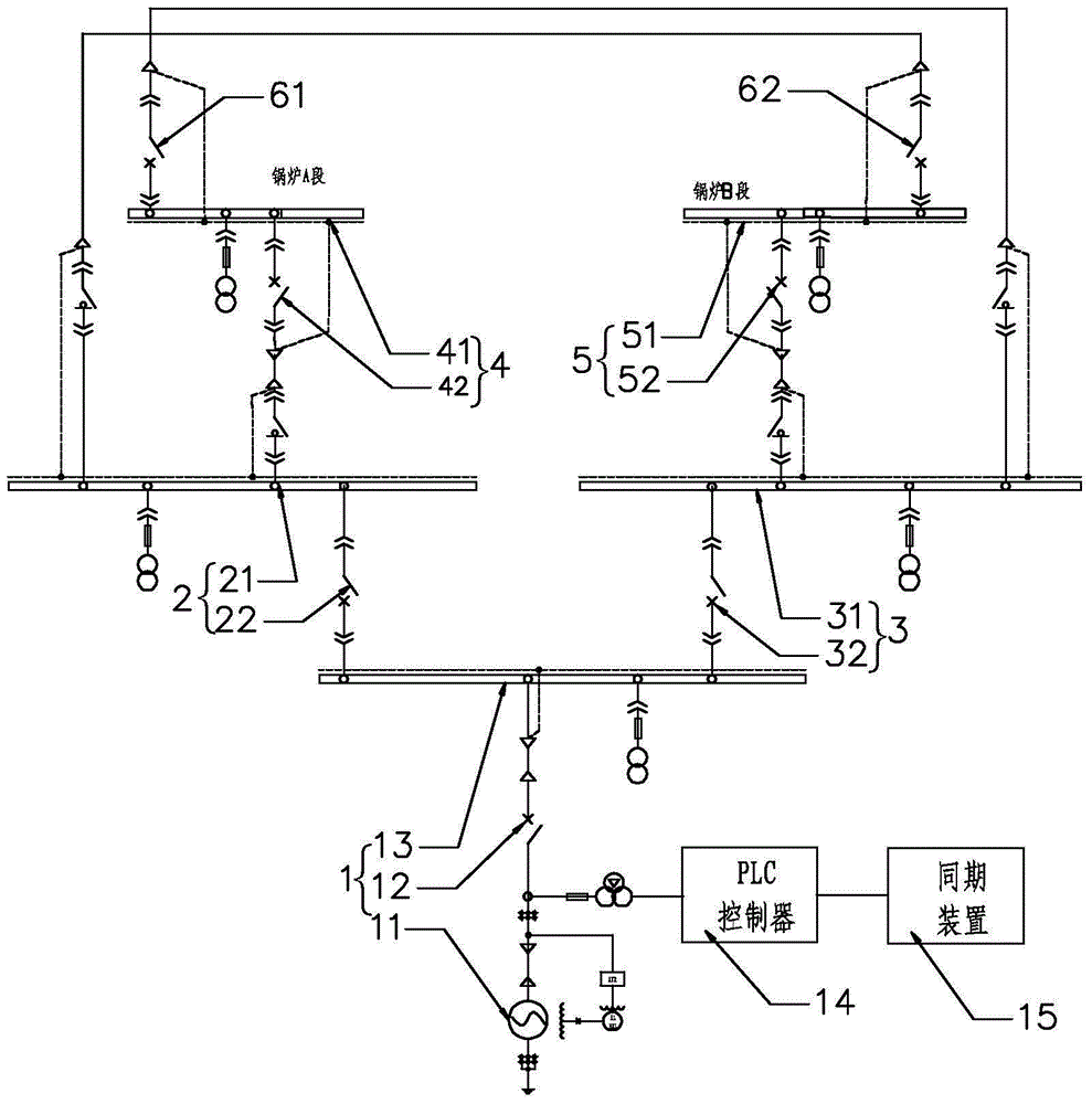
[0033] see figure 1 In order to better understand the technical solution of the present invention, the inventors of the present invention will describe in detail below through specific embodiments in conjunction with the accompanying drawings:

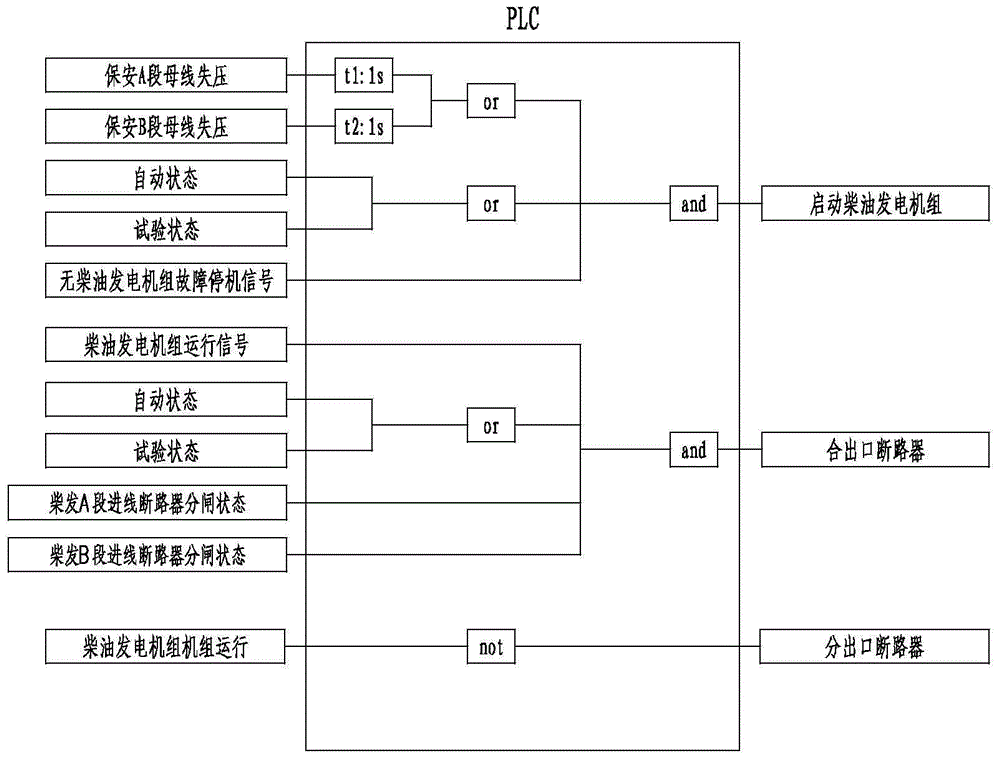
[0034] see figure 1, a kind of diesel generating set paralleling system for thermal power plant security power source of the present invention comprises diesel generating set 1, security A section 2, security B section 3, boiler A section 4 and boiler B section 5. The diesel generator set 1 includes a generator 11 and an outlet circuit breaker 12 , and the outlet side of the generator 11 is connected to a power distribution bus 13 through the outlet circuit breaker 12 . Meanwhile, a current transformer, a voltage transformer (not shown in the figure), a PLC controller 14 , and a synchronization device 15 connected to the PLC controller 14 are also connected to the outlet side of the generator 11 . The diesel generator set 1 is referr...


PUM


Abstract

The invention discloses a diesel generating set parallel operation system for a safety source of a thermal power plant. The diesel generating set parallel operation system comprises a diesel generating set, a safety section A, a safety section B, a boiler section A and a boiler section B, wherein the diesel generating set is provided with a PLC and a synchronizing device, and the PLC is connected with a central control room; an outlet circuit breaker is arranged at the outlet side of the diesel generating set and is connected with a power distribution bus; the safety section A comprises a safety section A bus and a diesel generating set section A incoming circuit breaker connected with the power distribution bus and the safety section A bus; the safety section B comprises a safety section B bus and a diesel generating set section B incoming circuit breaker connected with the power distribution bus and the safety section B bus; the boiler section A comprises a boiler section A bus and a section A working circuit breaker connected with the boiler section A bus and the safety section A bus; the boiler section B comprises a boiler section B bus and a section B working circuit breaker connected with the boiler section B bus and the safety section B bus; a standby second A circuit breaker is connected between the safety section A bus and the boiler section B bus; and a standby second B circuit breaker is connected between the safety section B bus and the boiler section A bus.

Description

technical field [0001] The invention relates to a diesel generating set paralleling system for thermal power plant security power supply in the field of power generation. Background technique [0002] Thermal power plant security power supply refers to the power supply to the accident security load set up to prevent the unit from being out of control, damaging the equipment, and affecting the power plant's long-term failure to restore power supply when the thermal power plant is out of power due to an accident. As the last line of defense for thermal power plants to protect important equipment such as units, whether the security power supply can operate reliably and stably is crucial to whether the diesel generator set can be quickly and correctly started and automatically switched on when the unit fails and causes a power outage in the whole plant. [0003] At present, special-purpose diesel generator sets are commonly used in domestic and foreign power plants as AC acciden...

Claims


Application Information

Patent Timeline
IPC IPC(8): H02J3/38H02J9/08
Inventor 田智会庄衍平许乃强
Owner SHANGHAI COOLTECH POWER
Learn More